Urility grid vertical axis wind turbine system

a vertical axis, wind turbine technology, applied in the direction of renewable energy generation, electric generator control, greenhouse gas reduction, etc., can solve the problems of affecting the environmental protection of homes or businesses, requiring massive construction projects, and affecting the access of wind energy to homes or businesses, so as to reduce the environmental footprint, attract investment potential, and reduce the effect of environmental footprin

Inactive Publication Date: 2011-03-17
ASTRAVENTUS
View PDF9 Cites 22 Cited by
  • Summary
  • Abstract
  • Description
  • Claims
  • Application Information

AI Technical Summary

Benefits of technology

[0013]It is another object of the present invention to provide a wind power energy system which provides an attractive investment potential, is simple in design, deployment, and use, but which does not expand the environmental foot-print.
[0014]It is another object of the present invention to provide a wind power energy system which is capable deployment in retrofit applications on existing utility grid supporting structures.
[0015]It is yet another object of the present invention to provide an integrated large or small wind power infrastructure that is easily connected to multiple direct sources or various grid interconnection points.
[0016]To overcome the problems associated with the prior art methods, and in accordance with the purpose of the present invention, as embodied and broadly described herein, briefly a vertical axis wind system for generation and distribution of electrical energy to a utility grid is provided. The system includes a power pole electricity system supported by a plurality of ground-based upright support members. The electricity system is electrically connected to the utility grid. The support members include at least one vertical rotor shaft portion. The rotor shaft portion has an outer surface and a vertical axis of rotation. A vertical axis wind turbine is rotatably attached to the rotor shaft portion so that the wind turbine rotates freely around the outer surface of the rotor shaft portion. A power take-off, is coupled to the wind turbine for driving a generator electrically connected to the utility grid when exposed to an atmospheric wind condition.

Problems solved by technology

In large wind installations, in the magnitude of 100 foot or more, giant sized turbines often dot the landscape and compromise the environment.
Such large turbines are typically deployed in remote areas, far away from the public infrastructure, and require massive construction projects for their interconnection back to the existing grid.
As a result, these installations are deployed far from the utility grid making which makes access of wind energy to homes or businesses very difficult.
Finally, with a large wind turbine system an enormous investment is required.
However, such investments have recently been viewed as a poor investment because they will simply not generate enough power when exposed to the constant changes in atmospheric wind conditions.
Such isolated deployments are therefore not useful in carrying out the direct powering of homes and business over large areas of land, or in establishing connection points to the utility grid.
While the foregoing example offers some utility, a major disadvantage with this application lies in the fact that, while it does provide for an additional beneficial use of the existing roadway electrical grid, it continues in the past practice of requiring the construction of a network of wind turbine machines, together with all of their associated ground based supporting structures, and points of connection for installation along predetermined positions of the roadway.

Method used


Image

  • Urility grid vertical axis wind turbine system
  • Urility grid vertical axis wind turbine system
  • Urility grid vertical axis wind turbine system

Examples


Embodiment Construction

[0027]Unless specifically defined otherwise, all technical or scientific terms used herein have the same meaning as commonly understood by one of ordinary skill in the art to which this invention belongs.

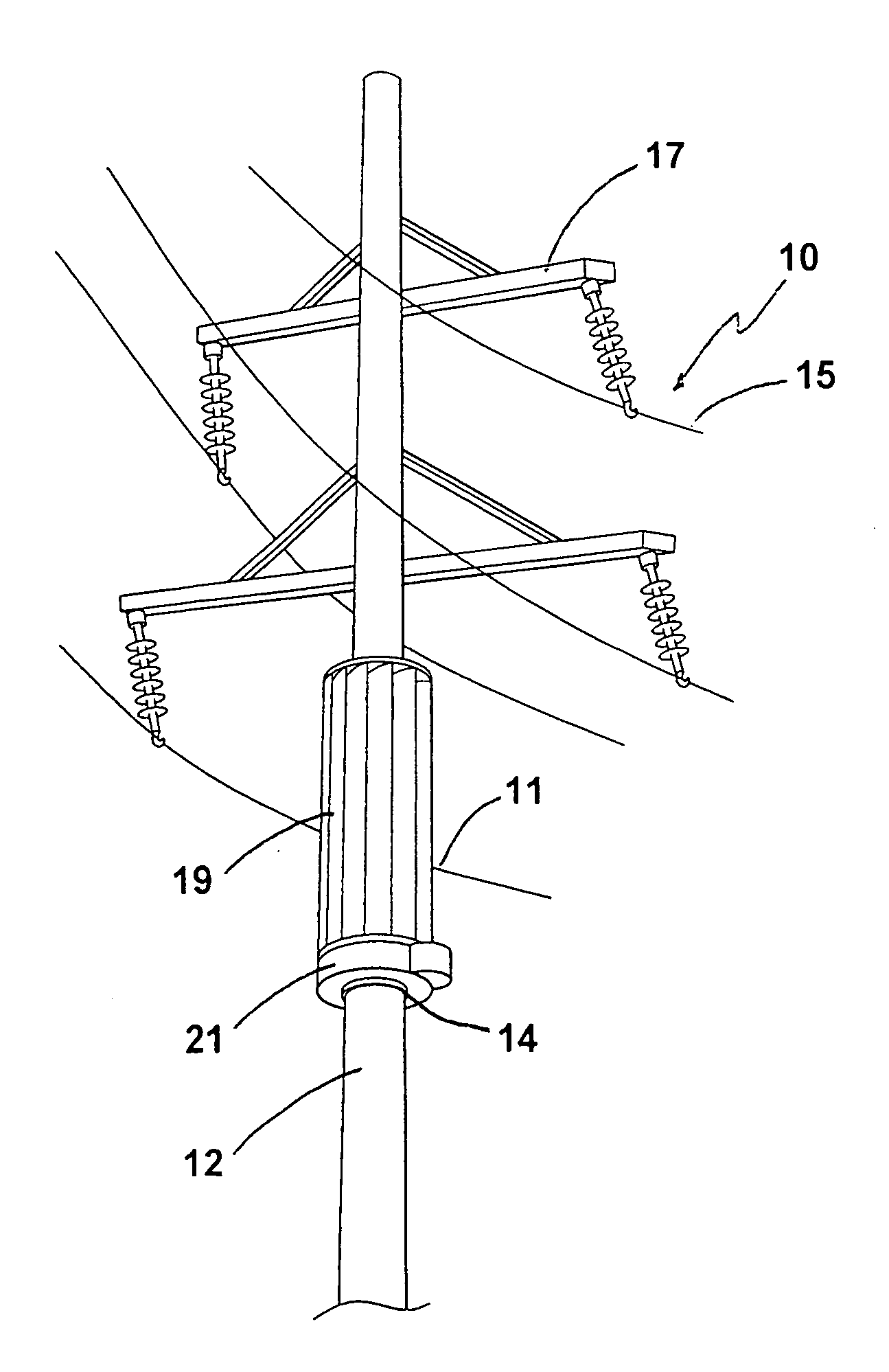
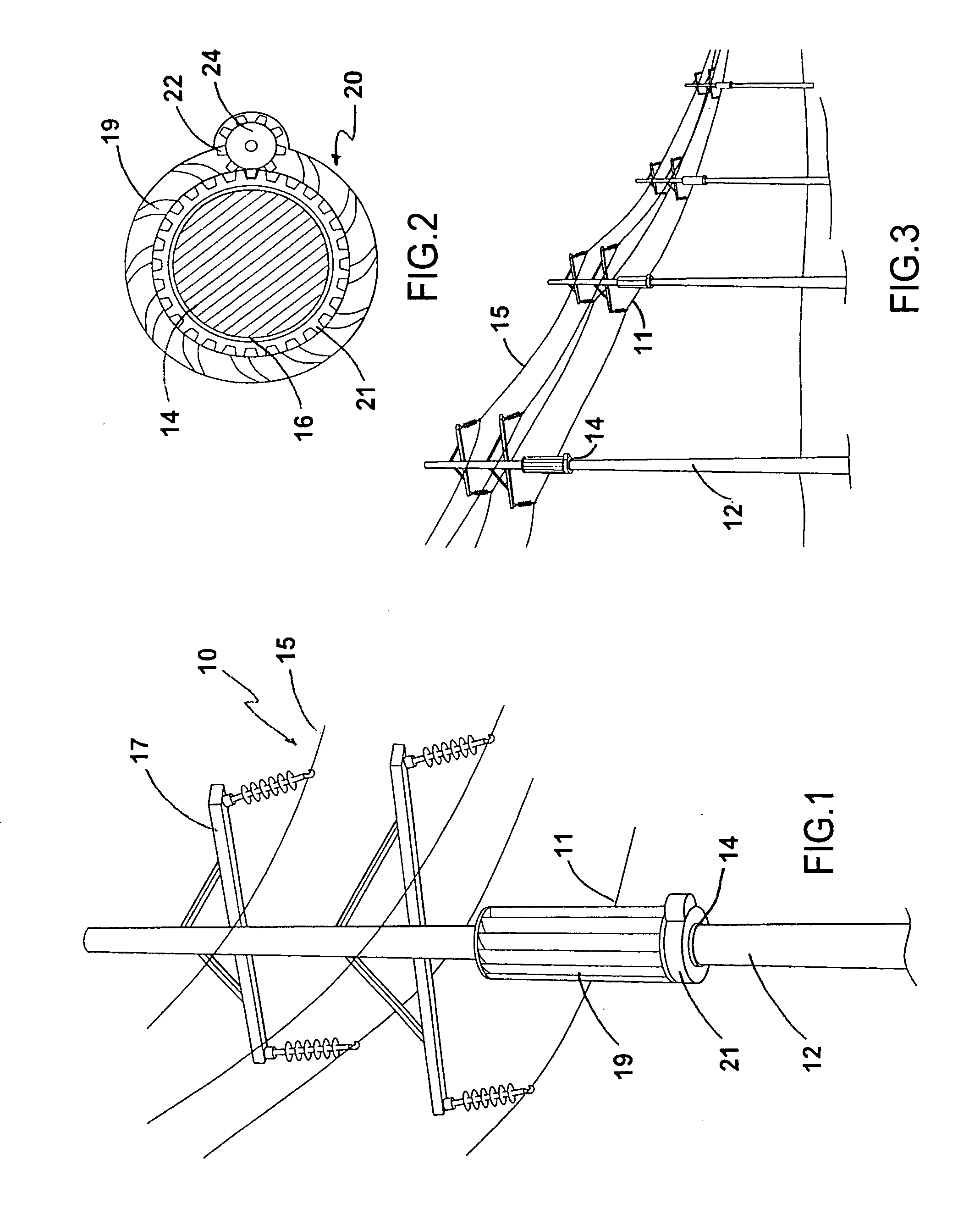
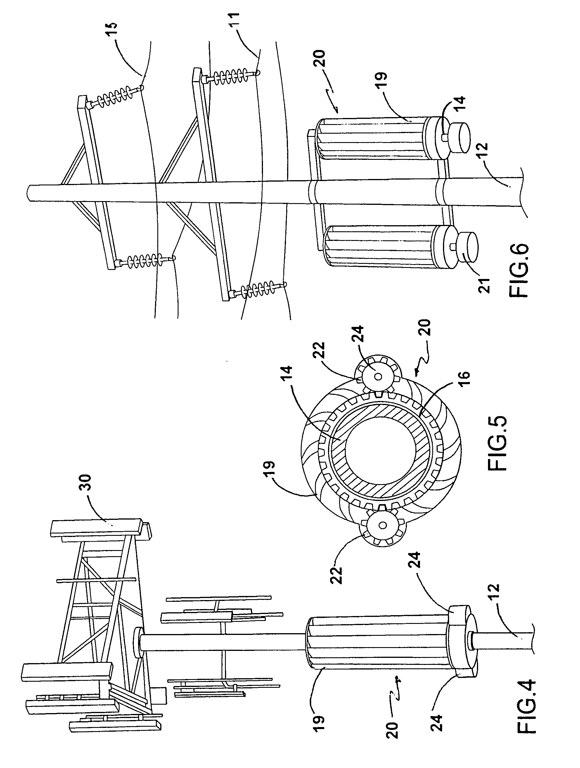
[0028]A “wind turbine array” means a plurality of wind energy generating devices either on a network of power poles, or on a single power pole.

[0029]An “electricity system” means a ground based network of electrical connections for the transportation and transmission of electrical energy, and may, but need not, include, energy storage systems, controls for inverting energy, power source changing units, electricity meters, and backup power systems.

[0030]The “utility grid” or “grid” means, the existing infrastructure of electrical lines and power boxes, as further described below.

[0031]An “energy storage system” as used herein is any device that can store electrical energy including, without limitation, systems which transform electrical energy into some other form of energy such as c...


PUM


Abstract

A vertical axis wind system for generation and distribution of electrical energy to a utility grid is provided. The system includes a power pole electricity system supported by a plurality of ground-based upright support members. The electricity system is electrically connected to the utility grid. The support members include at least one vertical rotor shaft portion. The rotor shaft portion has an outer surface and a vertical axis of rotation. A vertical axis wind turbine is rotatably attached to the rotor shaft portion so that the wind turbine rotates freely around the outer surface of the rotor shaft portion. A power takeoff is coupled to the wind turbine for driving a generator electrically connected to the utility grid when exposed to an atmospheric wind condition.

Description

CROSS REFERENCE TO RELATED APPLICATIONS[0001]This application is a national stage application which claims the benefit of International Application No. PCT / US2009 / 004413, filed 31 Jul. 2009.STATEMENT OF FEDERALLY SPONSORED RESEARCH[0002]Not applicable.BACKGROUND OF THE INVENTION[0003]1. Field of the Invention[0004]The present invention relates to wind power and distribution. In particular, it relates to a vertical axis wind turbine system deployed on the power grid for converting energy extracted from atmospheric wind into electrical energy transmitted to the power grid.[0005]2. Description of the Related Art[0006]Vertical axis wind turbines are well known in the art for extracting energy from atmospheric wind, and converting that energy, into electrical energy. Wind power turbines have been shown to be capable of generating power for delivery, via interconnection, to existing grid systems, individual homes, businesses, or utilities. Most of all of the wind power systems are designe...

Claims


Application Information

Patent Timeline
Patent Type & Authority Applications(United States)
IPC IPC(8): F03D9/00F03D3/00
CPCF03D3/005F03D11/04F05B2240/9121Y02E10/74Y02B10/30Y02E10/728F05B2240/913F03D13/20F03D9/43F03D80/70F03D9/255
Inventor PRICE, JR., ARNOLD
Owner ASTRAVENTUS
Why Eureka
Try Eureka