
Close proximity grinder

a grinder and close proximity technology, applied in the direction of highways, surface mining, road maintenance, etc., can solve the problems of not being suited to performing certain grinding functions, not having sufficient power or mass for pavement grinding, and affecting the operation of grinders, etc., to achieve tight turning radius and improve maneuverability

Active Publication Date: 2011-03-17
DIAMOND SURFACE
View PDF65 Cites 0 Cited by
  • Summary
  • Abstract
  • Description
  • Claims
  • Application Information

AI Technical Summary

Benefits of technology

Enables efficient and even grinding of curbs in a single pass, improving speed and quality while maintaining proper drainage, and reducing the need for manual operation.

Problems solved by technology

Such saws typically have a narrow cut and do not have sufficient power or mass for pavement grinding.
Although these grinding and cutting devices have proven to be useful and efficient for their intended purposes, they are not suited for performing certain grinding functions.
Challenges exist for close proximity grinding by curbs and drains as most large grinders cannot get sufficiently close to the curb.
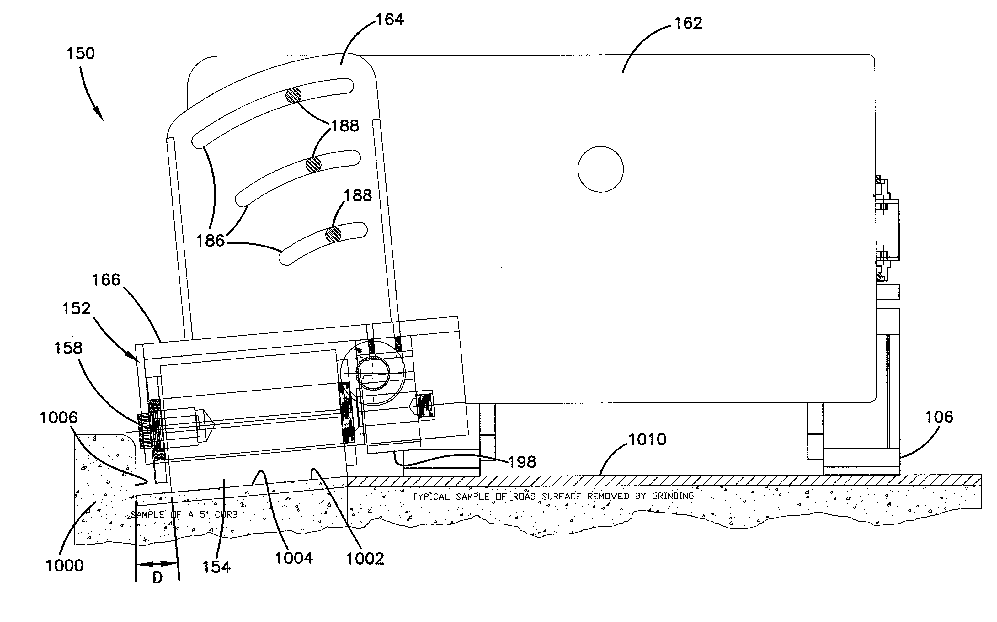
A further problem compounding the difficulty in grinding close to curbs and drains is the angle between the lower apron or drainage portion to be ground next to the curb wall and the surface of the road or street.
This causes problems for grinding the lower apron portion of the curb as the grinder has an arbor extending at an angle to this lower surface rather than being parallel with the surface of the lower drainage portion of the curb, as is required for satisfactory grinding.
In addition, grinding such curbs presents problems with regard to grinder access.
A common problem with such curbs is that a section of the drainage curb portion is slightly raised and / or offset, often leading to pooling and interrupting proper drainage.
Smaller prior art devices have not had the power and width to grind the surface of such portions in a satisfactory manner.
Such manual devices have not been satisfactory, as the grinding is uneven and the process is too time-consuming and inefficient due to the grinding head being too narrow with insufficient power.
The larger pavement grinding devices have arbors that do not get sufficiently close to the vertical portion of the curb to perform the grinding operation correctly.
Such an arrangement does not allow access to the curb to grind even a portion of the curb.

Method used


Image

  • Close proximity grinder
  • Close proximity grinder
  • Close proximity grinder

Examples


Embodiment Construction

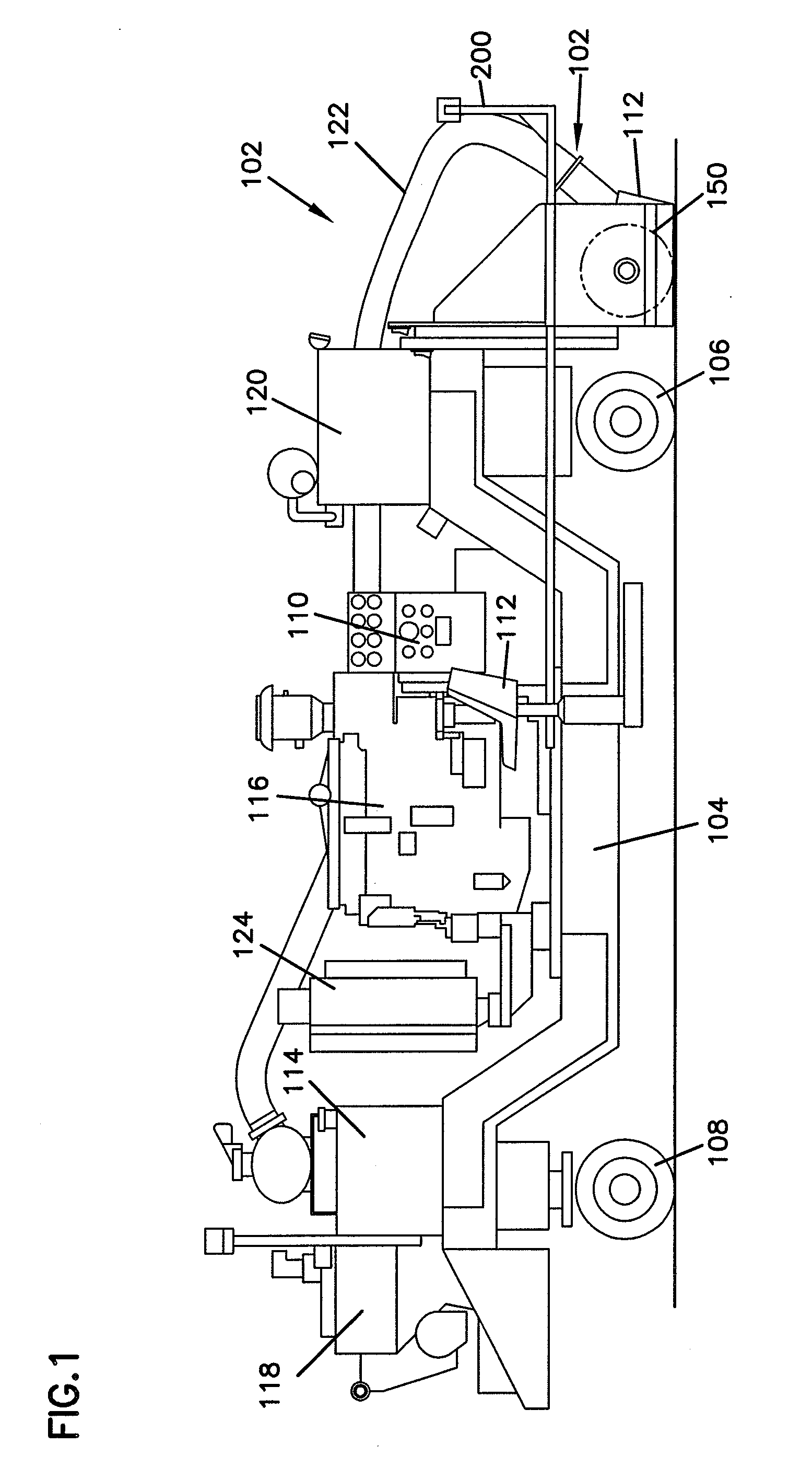
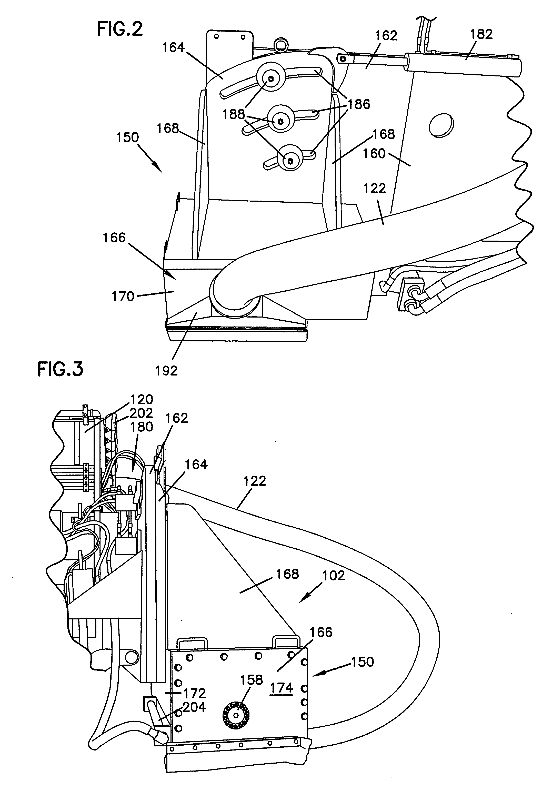
[0023]Referring now to the drawings and in particular to FIG. 1, there is shown a grinder, generally designated 100. The grinder 100 is configured for close proximity grinding by a laterally extending grinder assembly 102 and for grinding surfaces that are angled relative to the surface upon which the grinder 100 travels. Such grinding is needed for curbs at the edge of a road or street. The grinder 100 generally includes a frame 104 supported on front wheels 106 and rear wheels 108. In one embodiment, the front wheels 106 and rear wheels 108 are both steerable for improved maneuverability to closely follow a curb at the edge of the road. The front wheels 106 and rear wheels 108 may be steered in coordinated opposite directions for a tighter turning radius than is possible with other grinders and conventional two-wheel steering arrangements.

[0024]The grinder also has operational systems that are conventionally used with other types of pavement grinders. The grinder 100 includes an e...


PUM


Abstract

A close proximity pavement grinder is utilized for grinding close to a raised structure such as a lower surface of curbs close to the curb wall. The grinding apparatus utilizes a wide grinding head with grinding blades mounted along the length of an arbor to grind the lower surface of the curb in a single pass. The grinder includes a narrow bearing and support at the outer end of the arbor and is driven at the inner end so that the grinding may be conducted within close proximity of the curb wall. The grinder has a pivoting grinding head that can be locked at various angles relative to the grinder to match the relative angles between the pavement and the lower surface of the curb.

Description

BACKGROUND OF THE INVENTION[0001]1. Field of the Invention[0002]The present invention is directed to a grinding apparatus and method, and in particular to a pavement grinding apparatus and method for grinding close to curbs and other raised structures.[0003]2. Description of the Prior Art[0004]Pavement grinders are used for grinding concrete and asphalt surfaces to remove irregularities in the road surface, to provide texture to the surface to prevent skidding and to groove the surface to facilitate water drainage. Grinding, texturing and grooving are used on pavement surfaces including roads and streets, airport runways and bridge decks, industrial plants, stock pens and barns. The diamond tip blades that are used to grind the concrete or asphalt surfaces are mounted on a rotating arbor. Typical grinding machines have the arbor mounted on an under carriage so that both ends of the arbor are supported by bearing assemblies capable of sufficiently supporting the arbor while enduring ...

Claims


Application Information

Patent Timeline
Patent Type & Authority Applications(United States)
IPC IPC(8): E01C23/12
CPCE01C2301/50E01C23/088
Inventor KRAEMER, TERRENCE L.NESTEL, GERALD
Owner DIAMOND SURFACE
Learn More