
Lumped cross-coupled wilkinson circuit

Active Publication Date: 2011-03-17
QORVO US INC
View PDF3 Cites 8 Cited by
  • Summary
  • Abstract
  • Description
  • Claims
  • Application Information

AI Technical Summary

Benefits of technology

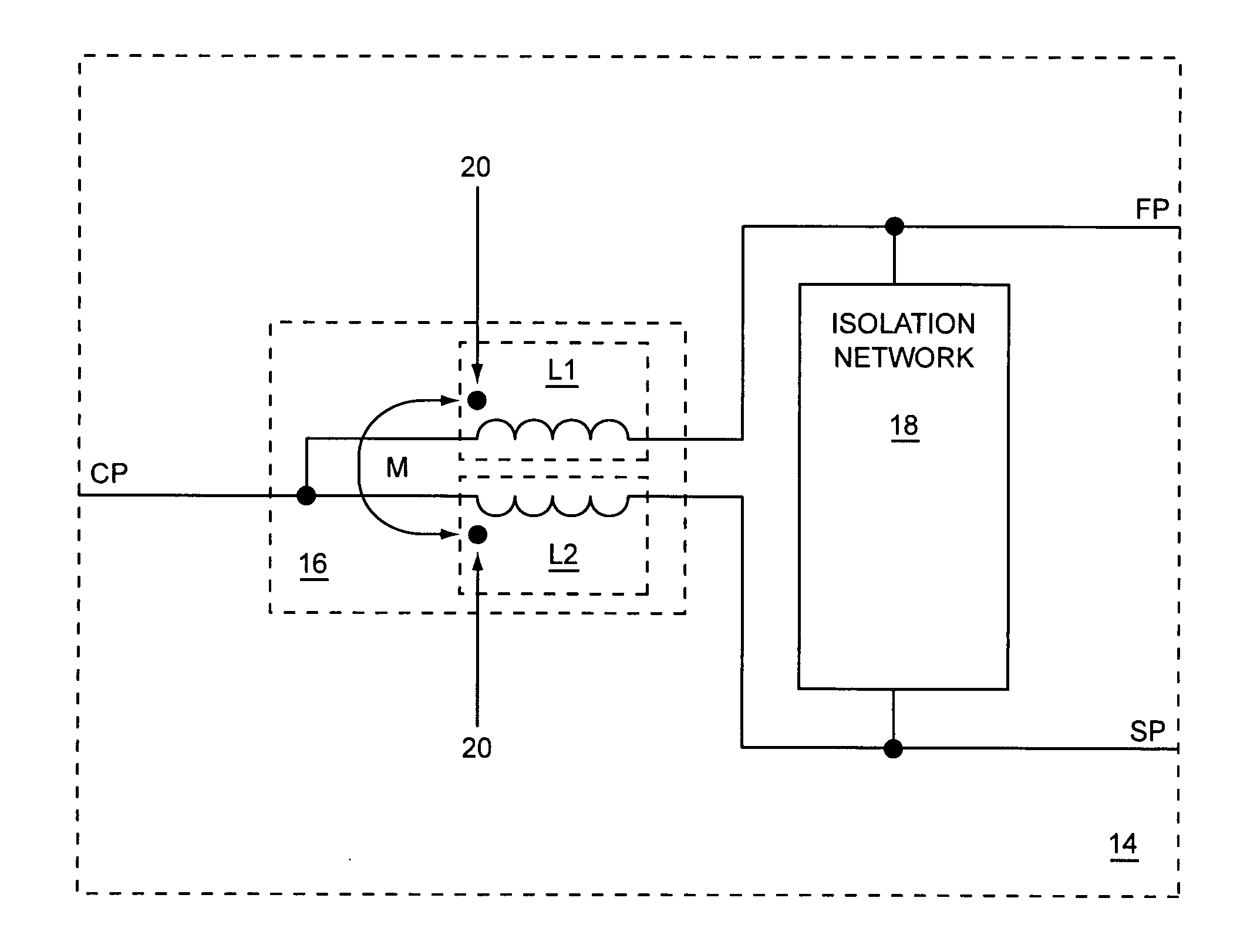
The present invention relates to a lumped cross-coupled Wilkinson circuit having a pair of magnetically cross-coupled inductive elements coupled to an isolation network. By magnetically cross-coupling the inductive elements, which have a mutual inductance, the inductance of each inductive element may be significantly less than the inductance of each inductive element in an equivalent lumped traditional Wilkinson combiner. Since the inductance of each inductive element is less, the size of each inductive element may be significantly smaller and the resistive loss of each inductive element may be significantly smaller. In one embodiment of the present invention, the lumped cross-coupled Wilkinson circuit operates as a lumped cross-coupled Wilkinson combiner. In an alternate embodiment of the present invention, the lumped cross-coupled Wilkinson circuit operates as a lumped cross-coupled Wilkinson splitter.

Problems solved by technology

The larger inductances require more area and have larger resistive losses.

Method used


Image

  • Lumped cross-coupled wilkinson circuit
  • Lumped cross-coupled wilkinson circuit
  • Lumped cross-coupled wilkinson circuit

Examples


Embodiment Construction

The present invention relates to a lumped cross-coupled Wilkinson circuit having a pair of magnetically cross-coupled inductive elements coupled to an isolation network. By magnetically cross-coupling the inductive elements, which have a mutual inductance, the inductance of each inductive element may be significantly less than the inductance of each inductive element in an equivalent lumped traditional Wilkinson combiner. Since the inductance of each inductive element is less, the size of each inductive element may be significantly smaller and the resistive loss of each inductive element may be significantly smaller. In one embodiment of the present invention, the lumped cross-coupled Wilkinson circuit operates as a lumped cross-coupled Wilkinson combiner. In an alternate embodiment of the present invention, the lumped cross-coupled Wilkinson circuit operates as a lumped cross-coupled Wilkinson splitter.

The lumped cross-coupled Wilkinson combiner may be used to combine quadrature RF...


PUM


Abstract

The present invention relates to a lumped cross-coupled Wilkinson circuit having a pair of magnetically cross-coupled inductive elements coupled to an isolation network. By magnetically cross-coupling the inductive elements, which have a mutual inductance, the inductance of each inductive element will be significantly less than the inductance of each inductive element in an equivalent lumped traditional Wilkinson combiner. Since the inductance of each inductive element is less, the size of each inductive element may be significantly smaller and the resistive loss of the each inductive element may be significantly smaller. In one embodiment of the present invention, the lumped cross-coupled Wilkinson circuit operates as a lumped cross-coupled Wilkinson combiner. In an alternate embodiment of the present invention, the lumped cross-coupled Wilkinson circuit operates as a lumped cross-coupled Wilkinson splitter.

Description

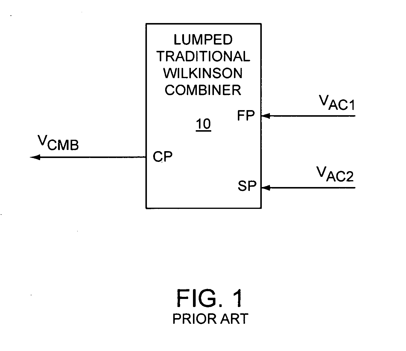
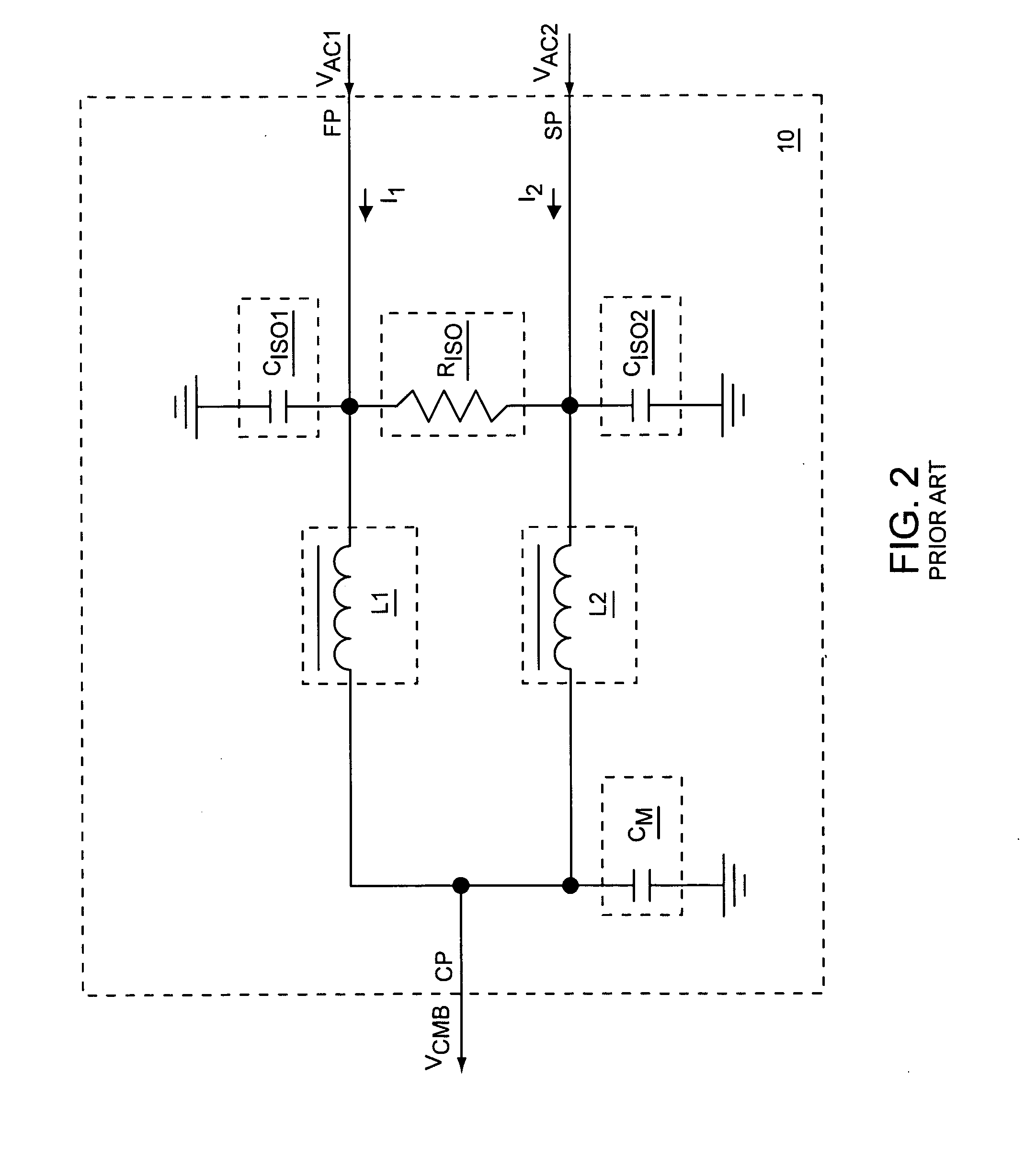
FIELD OF THE INVENTIONEmbodiments of the present invention relate to lumped Wilkinson combiners and splitters, which may be used in radio frequency (RF) communications circuits.BACKGROUND OF THE INVENTIONWilkinson combiners are used to combine two alternating current (AC) signals with a combined AC signal, whereas Wilkinson splitters are used to split an AC signal into two AC signals. Some Wilkinson combiners may be used as Wilkinson splitters, and vice versa. FIG. 1 shows a lumped traditional Wilkinson combiner 10 according to the prior art. The lumped traditional Wilkinson combiner 10 may include a first port FP and a second port SP for receiving a first AC signal VAC1 and a second AC signal VAC2, respectively, and a common port CP for providing a combined AC signal VCMB, which is based on combining the first AC signal VAC1 and the second AC signal VAC2. At certain frequencies and in certain circuit arrangements, the lumped traditional Wilkinson combiner 10 may provide impedance m...

Claims


Application Information

Patent Timeline
IPC IPC(8): H03H7/38
CPCH03H7/48H03H7/09
Inventor JONES, DAVID E.HOHEISEL, KEVIN M.
Owner QORVO US INC
Learn More