Cooling pump unit and projection display apparatus including the same

a technology of projection display and pump unit, which is applied in the direction of pump components, positive displacement liquid engines, instruments, etc., can solve the problems of noise generation and noise generation, and achieve the effects of reducing the buffer performance of the cushions, reducing the length of the communication tube, and increasing nois

Inactive Publication Date: 2011-03-17
NEC DISPLAY SOLUTIONS LTD
View PDF11 Cites 2 Cited by
  • Summary
  • Abstract
  • Description
  • Claims
  • Application Information

AI Technical Summary

Benefits of technology

[0015]When the frictional forces are smaller than the force of the first direction, main pump body 501 moves in the first direction. The movement of main pump body 501 causes wear of cushions 513a and 513b on the contacted portions. When the pump stops, the temperature of communicating tube 503 drops due to natural cooling, which is accompanied by a reduction in communicating tube length A. In this case, force is applied in a second direction reverse to the first direction to move main pump body 501 in the second direction. This movement of main pump body 501 also causes wear of cushions 513a and 513b on the contacted portions. Thus, when the pump is driven or stopped, main pump body 501 moves in the first or second direction, causing wear of cushions 513a and 513b. With further wear of cushions 513a and 513b, the buffer performance of the cushions is reduced. This results in a problem in which noise is generated because of insufficient absorption of the vibration of the pump by cushions 513a and 513b.
[0016]Vibration during transport causes movement of main pump body 501, which results in the wear of cushions 513a and 513b. This wear increases noise.
[0017]It is an object of the present invention to provide a pump unit capable of solving the abovementioned problems and suppressing generation of noise caused by crushing or wear of cushions, and a projection display apparatus.

Problems solved by technology

However, the pump unit described in JP2008-96459A has the following problems.
This results in a problem in which noise is generated because of insufficient absorption of the vibration of the pump by cushions 513a and 513b.

Method used


Image

  • Cooling pump unit and projection display apparatus including the same
  • Cooling pump unit and projection display apparatus including the same
  • Cooling pump unit and projection display apparatus including the same

Examples


Embodiment Construction

[0065]Hereinafter, referring to the drawings, an embodiment of the present invention is described.

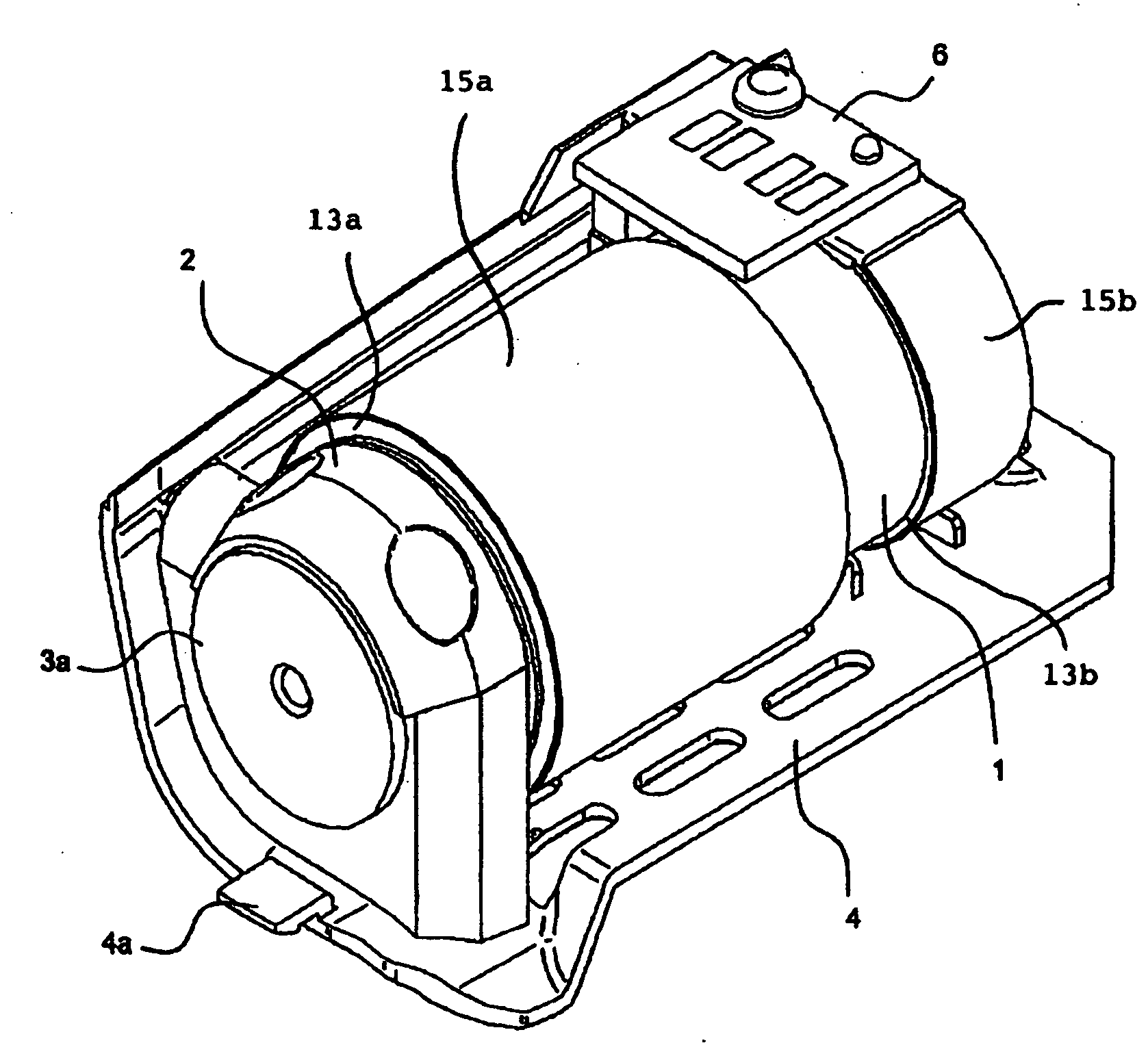
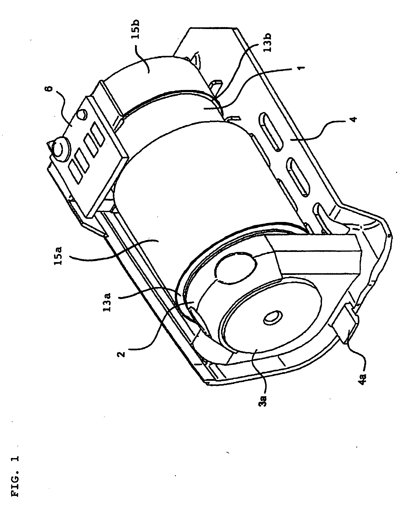
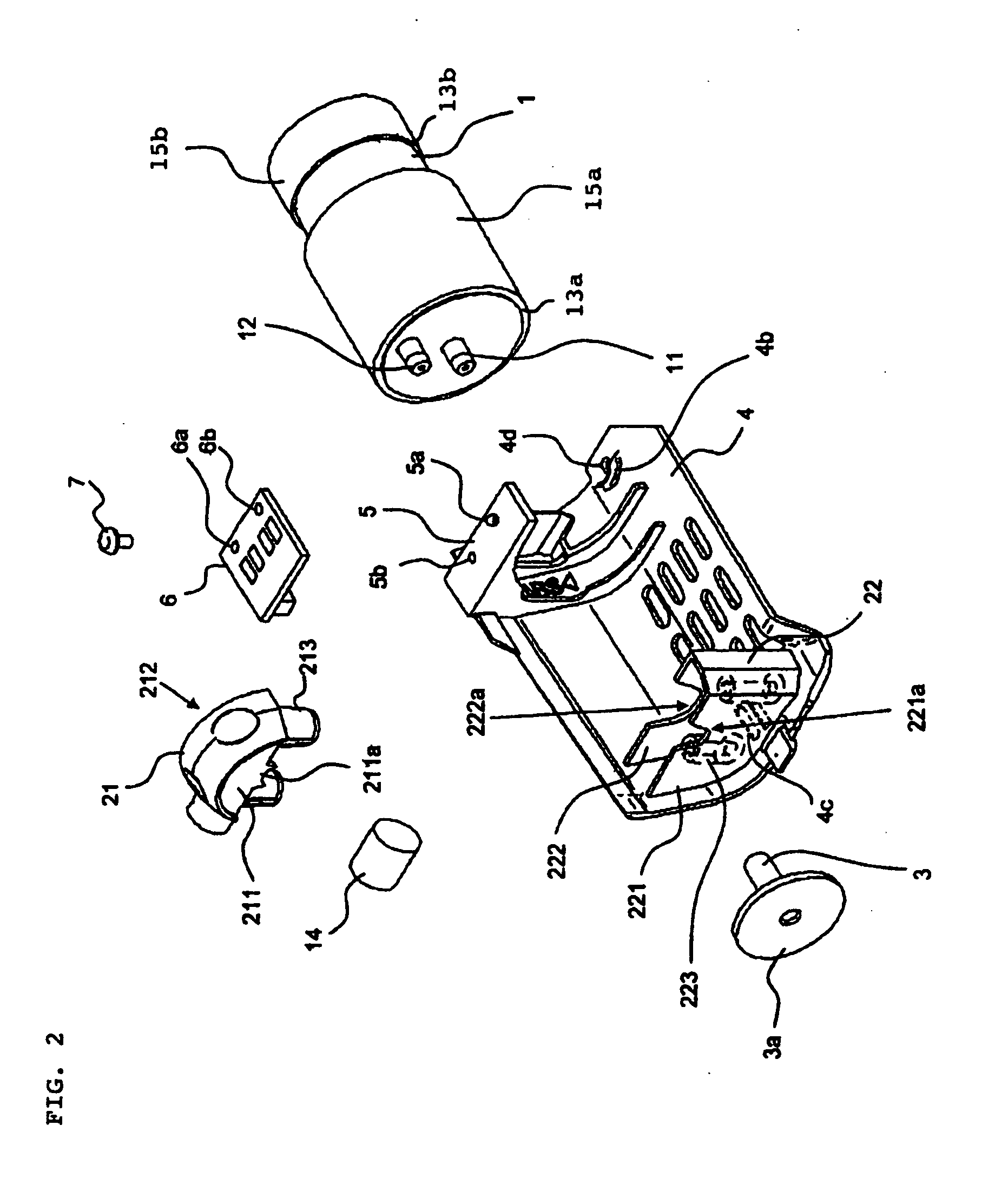
[0066]FIG. 1 is a perspective view showing a configuration of a pump unit according to the embodiment of the present invention, and FIG. 2 is an exploded perspective view of the pump unit shown in FIG. 1.

[0067]Referring to FIG. 1 and FIG. 2, the pump unit is a detachable unit attached to a casing of an electronic device that includes a heat source such as a light source. A main portion thereof includes main pump body 1, pump fixing portion 2, communicating tube 3, and cover 4. Main pump body 1 is a pressure pump such as a diaphragm pump.

[0068]A portion of main pump body 1 likely to come into contact with other members is covered with a cushion member serving as a buffer member. The cushion member is made of an elastomer such as spongy rubber or a synthetic resin (foam material) capable of absorbing vibration or shocks. In FIG. 1, an outer circumferential surface of main pump body 1 is c...


PUM


Abstract

Generation of noise is suppressed by solving the problems of crushing and wear of a cushion caused by thermal expansion of a communicating tube. A pump unit includes main pump body 1 for discharging compressed air, a communicating tube made of an elastomer and having its one end fitted to a discharge opening of the main pump body 1, pump fixing portion 2 for holding a part of a portion of the communicating tube other than its portion fitted to the discharge opening, cushions 13a and 13b arranged on an outer circumferential surface of main pump body 1, and films 15a and 15b arranged on surfaces of cushions 13a and 13b. Films 15a and 15b have smooth surfaces, and friction coefficients of the smooth surfaces are smaller than those of cushions 13a and 13b.

Description

TECHNICAL FIELD[0001]The present invention relates to a cooling pump unit of a projection display apparatus represented by a liquid crystal projector.BACKGROUND ART[0002]For a cooling apparatus of the projection display apparatus, a cooling pump such as a diaphragm pump is used. Generally, the pump has a usable life period. Thus, a cooling apparatus (cooling pump unit) of an exchangeable unit structure is used.[0003]The cooling pump vibrates during its operation. The vibration of the cooling pump is transmitted to the casing of the projection display apparatus to generate noise.[0004]Japanese Utility Model Application Laid-Open No. 05-13402 describes a pump fixing structure where measures have been taken against pump vibration. The pump fixing structure includes a pressure pump, a cushion material to cover the outer circumferential surface of the pressure pump, a receiving body having a surface on which a half surface of the outer circumference of the pressure pump covered with the ...

Claims


Application Information

Patent Timeline
Patent Type & Authority Applications(United States)
IPC IPC(8): F04B43/08G03B21/16
CPCF04B39/06G03B21/16F04B45/04
Inventor LEE, JUNSI
Owner NEC DISPLAY SOLUTIONS LTD
Why Eureka
Try Eureka