Developing device and image forming apparatus

a technology of developing device and image forming apparatus, which is applied in the direction of electrographic process apparatus, instruments, optics, etc., can solve the problems of toner leakage, deterioration of sealing property, and leakage of developer, so as to prevent the contamination of the inside of the apparatus by toner

Inactive Publication Date: 2011-03-17
KONICA MINOLTA BUSINESS TECH INC
View PDF3 Cites 3 Cited by
  • Summary
  • Abstract
  • Description
  • Claims
  • Application Information

AI Technical Summary

Benefits of technology

[0036]Since the image forming apparatus of the invention includes the developing device, contamination of the inside of the apparatus by the toner can be prevented.

Problems solved by technology

There is a problem that the surface of the shaft section is abraded by the carrier invading in between the sealing member and the shaft section of the screw member, and this abrasion may deteriorate a sealing property, resulting in leakage of the developer.
However, in this configuration, a carrier seal cannot always be formed due to backlash of the shaft section of a screw member in an axial thrust direction, which causes a toner leakage problem.
Moreover, since no sealing member is provided therein, it is impossible to prevent toner leakage.
However in this configuration, a carrier seal cannot always be formed due to backlash of a shaft section of the screw member in an axial thrust direction, which causes a toner leakage problem.
Moreover, since no sealing member is provided therein, it is impossible to prevent toner leakage.
However in this configuration, since the sealing member is on the inner side of the magnet, a carrier invades in between the sealing member and a shaft section of the screw member, which makes it impossible to prevent the carrier from abrading the shaft section of the screw member, and the space for the buffer board goes to waste.

Method used


Image

  • Developing device and image forming apparatus
  • Developing device and image forming apparatus
  • Developing device and image forming apparatus

Examples


first embodiment

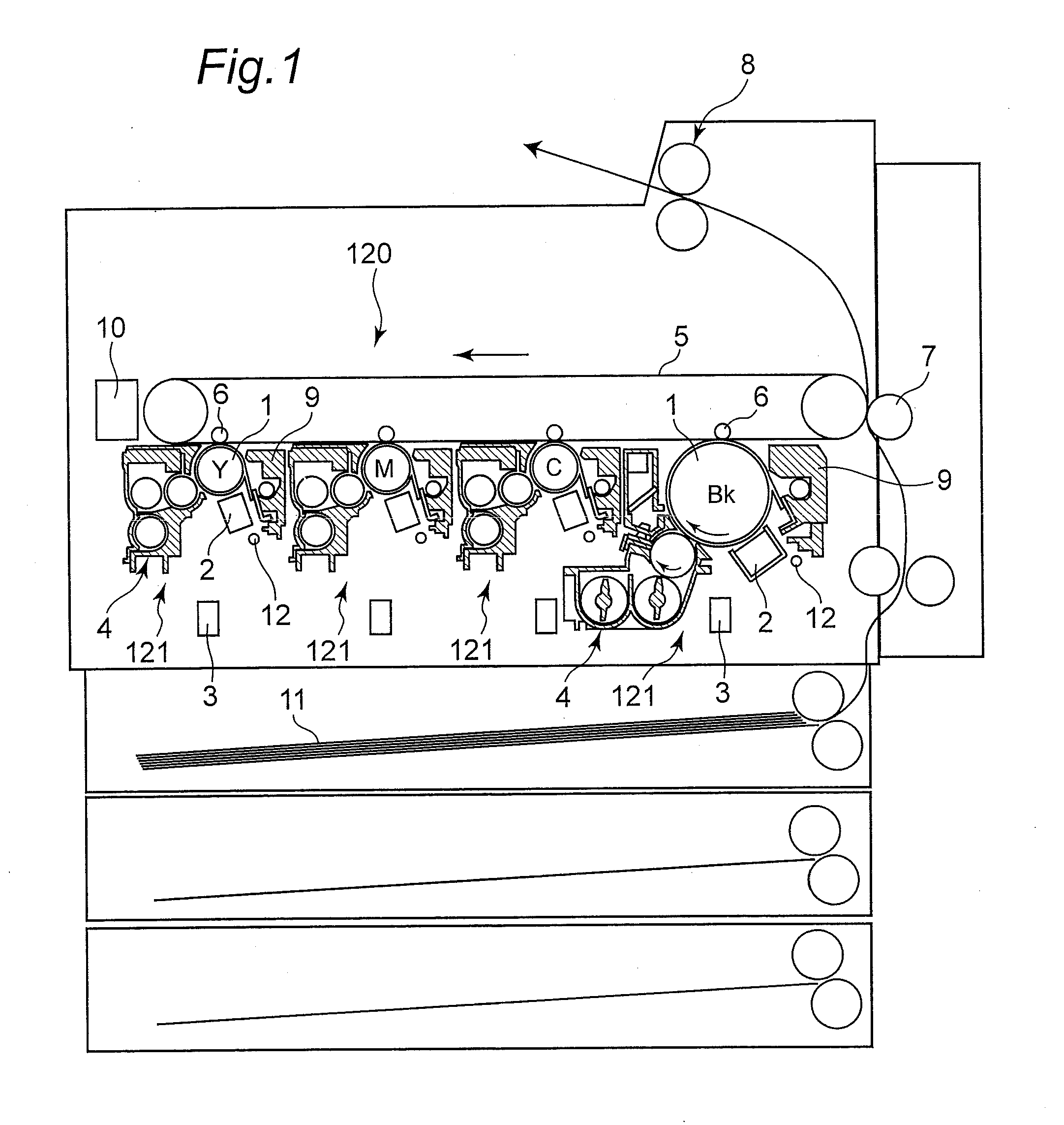
[0048]FIG. 1 is a simplified structure view of an image forming apparatus in one embodiment of the invention. This image forming apparatus is a full color electrophotographic apparatus having an imaging device 120 and a fixing device 8.

[0049]The imaging device 120 attaches an unfixed toner onto a recording medium 11 (e.g., paper) to form an image. The fixing device 8 melts the toner and fixes it to the recording medium 11.

[0050]The imaging device 120 is composed of a transfer belt 5, four image forming units 121 placed along the transfer belt 5, and a secondary transfer device 7 placed facing the transfer belt 5.

[0051]The image forming unit 121 forms a toner image, and transfers the toner image onto the transfer belt 5. The secondary transfer device 7 transfers the toner image, which was transferred onto the transfer belt 5, onto a recording medium 11.

[0052]An image forming unit 121 for forming toner images in black (Bk), an image forming unit 121 for forming toner images in yellow ...

second embodiment

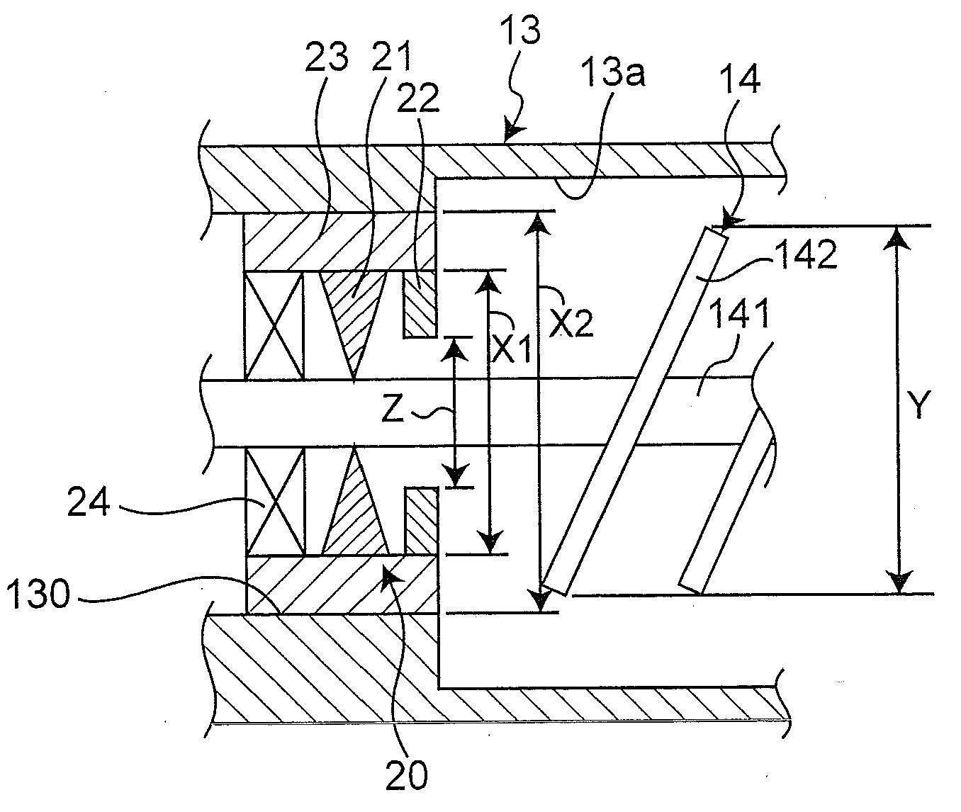
[0086]FIG. 5 shows a developing device in a second embodiment of the invention. The second embodiment is different from the first embodiment in the structure of the retaining section. It is to be noted that in the second embodiment, component members identical to those in the first embodiment are designated by identical reference numerals to omit detailed explanation.

[0087]As shown in FIG. 5, on the inner surface of the retaining member 23A, a flange 231 projecting radially inside is provided at a part inward in the longitudinal direction of the housing 13. The flange 231 covers a side surface 22a of the magnet 22 inward in the longitudinal direction of the housing 13.

[0088]An inner diameter X1 of the retaining member 23A inward in the longitudinal direction of the housing 13 is equivalent to an inner diameter of the flange 231, the inner diameter X1 being smaller than an inner diameter X2 of the hole section 130 of the housing 13 inward in the longitudinal direction of the housing ...

third embodiment

[0092]FIG. 6 shows a developing device in a third embodiment of the invention. The third embodiment is different from the first embodiment in the structure of the retaining section. It is to be noted that in the third embodiment, component members identical to those in the first embodiment are designated by identical reference numerals to omit detailed explanation.

[0093]As shown in FIG. 6, on the inner surface of a retaining member 23B, a bearing section 232 projecting radially inside is provided in a part inward in the longitudinal direction of the housing 13. The bearing section 232 holds the shaft section 141 of the agitating conveyance member 14 in place of the bearing member 24 of the first embodiment. The bearing section 232 is placed on the outer side of the sealing member 21 in the longitudinal direction of the housing 13.

[0094]In short, the retaining member 23B holds the sealing member 21 while holding the shaft section 141 of the agitating conveyance member 14.

[0095]In the...


PUM


Abstract

There is provided a developing device capable of preventing a carrier from abrading a shaft section of an agitating conveyance member facing a sealing member and preventing toner leakage resulting from the abrasion. A sealing member 21 is for sealing a clearance between a housing 13 and a shaft section 141 of an agitating conveyance member 14. A magnet 22 forms a magnetic shield in a radial direction orthogonal to the shaft section 141 of the agitating conveyance member 14. The magnet 22 is placed on the inner side of the sealing member 21 inside the housing 13.

Description

[0001]This application is based on application No. 2009-214194 filed in Japan on Sep. 16, 2009, the entire content of which is hereby incorporated by reference.BACKGROUND OF THE INVENTION[0002]1. Field of the Invention[0003]The present invention relates to a developing device for use in an electrophotographic image forming apparatus, and an image forming apparatus with use of the developing device.[0004]2. Description of the Related Art[0005]Electrophotographic image forming apparatuses generally include an image carrier, a charging device for uniformly charging the surface of the image carrier, an exposure device for forming an electrostatic latent image from electric charge on the image carrier, a developing device for forming a visible image from the electrostatic latent image on the image carrier with use of a developer, a transfer device for electrically and mechanically transferring the visible image on the image carrier onto a recording medium, a cleaning device for removing ...

Claims


Application Information

Patent Timeline
Patent Type & Authority Applications(United States)
IPC IPC(8): G03G15/08
CPCG03G15/0817
Inventor SAKURAI, HIDETO
Owner KONICA MINOLTA BUSINESS TECH INC
Why Eureka
Try Eureka