Medical fluid circuit comprising a low level detector 1

Active Publication Date: 2011-03-17
GAMBRO DASCO SPA
View PDF12 Cites 37 Cited by
  • Summary
  • Abstract
  • Description
  • Claims
  • Application Information

AI Technical Summary

Benefits of technology

[0014]An advantage of the invention is that it guarantees prompt triggering of an alarm signal in a case in which a faulty situation of excess air in a medical fluid circuit is detected.
[0015]A further advantage is that it makes available a medical fluid circuit which is constructionally simple and economical.
[0016]A still further advantage is that it gives rise to a monitoring system for a medical fluid circuit which is able to signal, in a timely and reliable way, an undesired situation of excess of air in the circuit itself, in particular during a replacement of an emptied source batch of medical fluid with a full one.
[0017]These aims and others besides are all attained by the object of the invention as it is characterised in one or more of the claims.
[0018]In a specific embodiment of the invention, a control unit of a medical fluid circuit is programmed to perform a monitoring process of the circuit comprising the following stages: displacing a certain quantity of fluid along a medical fluid supply line, measuring the pressure in an expansion chamber arranged on the supply line during the displacement, and recognising a faulty situation of excessive air presence in the expansion chamber if the pressure does not sufficiently lower. The displacement of the medical fluid can be optionally realised by means of a positive displacement pump, such as for example a wall-deforming pump. The medical fluid can be removed from a source batch of the fluid itself. The medical fluid circuit can optionally comprise a devi

Problems solved by technology

There can however be a certain lapse of time after effective emptying of the container and the moment the infusion pump halts, during which time the infusion pump can draw air instead of infusion fluid into the infusion line.
A drawbac

Method used


Image

  • Medical fluid circuit comprising a low level detector 1
  • Medical fluid circuit comprising a low level detector 1
  • Medical fluid circuit comprising a low level detector 1

Examples


Example

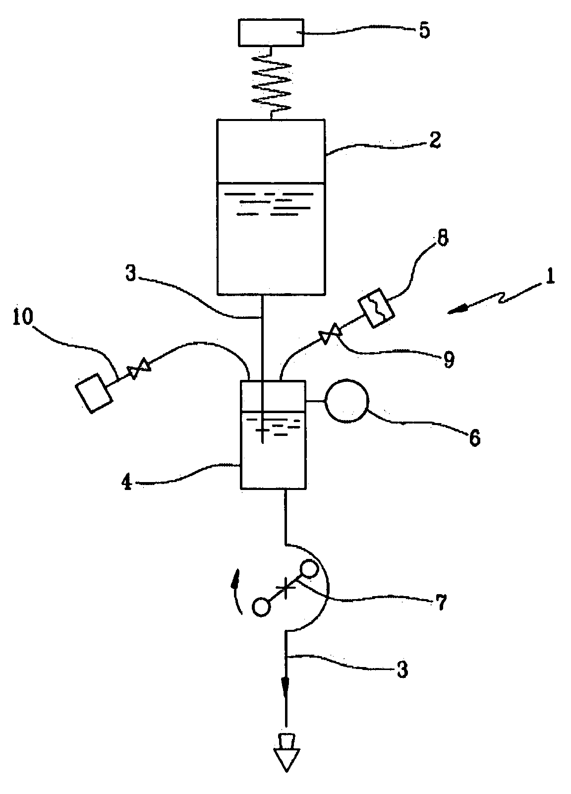
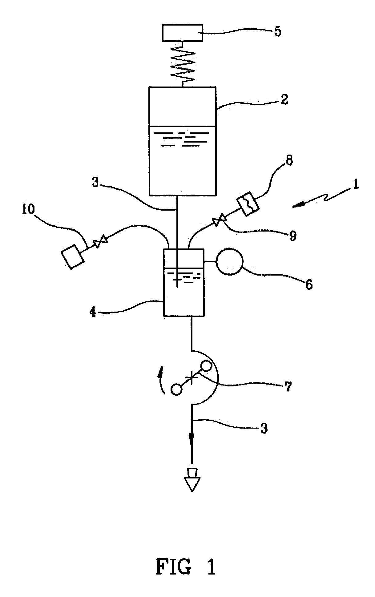
[0026]In FIG. 1, 1 is denoted in its entirety by an infusion circuit, 2 denotes a batch container for an infusion fluid, 3 an infusion line, 4 an expansion chamber, 5 a weight sensor, 6 a pressure sensor, 7 an infusion pump, 8 a hydrophobic filter applied to a vent of the chamber 4, 9 a block valve (clamp), 10 a service line for access to the chamber 4 (for example by means of a syringe).

[0027]The infusion circuit 1 can be directly associated to a vascular access of an individual, for example by direct infusion of a medical fluid. The infusion circuit 1 can be used to infuse a medical fluid in an extracorporeal blood circuit removing blood from a vascular access of an individual and returning it after carrying out a treatment (for example dialysis, hemofiltration, hemodiafiltration, pure ultrafiltration, therapeutic plasma exchange, hemoperfusion, treatment for hepatic failure, removal of some blood components, separation of some blood components, etc.).

[0028]The infusion fluid can ...


PUM


Abstract

In an infusion circuit (1), a peristaltic pump (7) displaced the infusion fluid along a line (3), sourcing it from a batch container (2). When a weight sensor (5) detects an emptying of the batch container (2), the pump is halted. If on stopping the pump the pressure measured by a sensor (6) operating in an expansion chamber (4) does not drop in excess of a predetermined threshold with respect to a non-empty container (2), a non-secure situation is signalled, due to an excessive quantity of air in the expansion chamber.

Description

BACKGROUND OF THE INVENTION[0001]The invention relates to a medical fluid circuit and a control method of a medical fluid circuit.[0002]Specifically, though not exclusively, the invention can be usefully applied in supplying a medical fluid, such as for example an infusion fluid or a dialysis fluid.[0003]In particular, the medical fluid circuit of the invention comprises a source batch of the medical fluid which during use is emptied and has to be replaced by another, full source batch.[0004]An infusion circuit is known which comprises an infusion pump that sources the infusion liquid from a batch container and sends it to an individual (directly into the body of the individual or via an extracorporeal blood circuit). Also known is using a monitoring system of the weight of the container used, for example a scales applied to the container. When the weight measured by the scales does not fall for a given period of time, the control unit of the infusion circuit signals that the contai...

Claims


Application Information

Patent Timeline
IPC IPC(8): A61M1/34
CPCA61M1/342A61M5/16845A61M2205/3393A61M2205/3386A61M5/1689
Inventor FRANZONI, GIUSEPPECALEFFI, LUCASAKOTA, RANKO
Owner GAMBRO DASCO SPA
Why Eureka
Try Eureka