Drain assembly, drain body for use in such an assembly and method for building-in of a drain

a technology of drain body and drain, which is applied in the direction of sewerage structure, sewer system, domestic plumbing, etc., can solve the problem of watertight connection between the drain and the tiles

Inactive Publication Date: 2011-03-24
N V STEYLAERTS
View PDF9 Cites 46 Cited by
  • Summary
  • Abstract
  • Description
  • Claims
  • Application Information

AI Technical Summary

Benefits of technology

[0005]The present invention has for its object to provide a drain assembly which can be placed easily and properly by a tiler and with which leakage and / or moisture problems can particularly be avoided.
[0011]A minimal overlap zone will typically be necessary along the whole outer periphery of the water-sealing layer in order to guarantee an adequate water sealing. Such a drain assembly will ensure that penetration of water due to capillary action in the tile floor is largely prevented. The water-sealing layer will more particularly provide for a good water sealing close to the drain, this without the tiler having to be particularly experienced. This water-sealing layer is after all pre-adhered watertightly to the peripheral flange, and the sufficient overlap between this layer and the water-sealing mat will in this way bring about an efficient sealing.
[0014]According to a preferred embodiment of the invention, the peripheral flange is provided close to the outer periphery thereof with an upright edge, this such that water seeping in along the sealing layer is held back by this upright edge. This will further improve the watertightness and reduce the overlap necessary in determined embodiments.
[0018]According to a further developed embodiment, the drain body can be provided on its underside with a number of protrusions for stabilizing the drain body during placing thereof in a floor material such as mortar. The inlet zone can further be provided on the inner side with one or more support edges for supporting a grate assembly along which the water flows from the floor to the inlet zone.

Problems solved by technology

A known problem of the existing drains for tile floors is associated with making the connections between the drain and the tiles watertight.

Method used


Image

  • Drain assembly, drain body for use in such an assembly and method for building-in of a drain
  • Drain assembly, drain body for use in such an assembly and method for building-in of a drain
  • Drain assembly, drain body for use in such an assembly and method for building-in of a drain

Examples


first embodiment

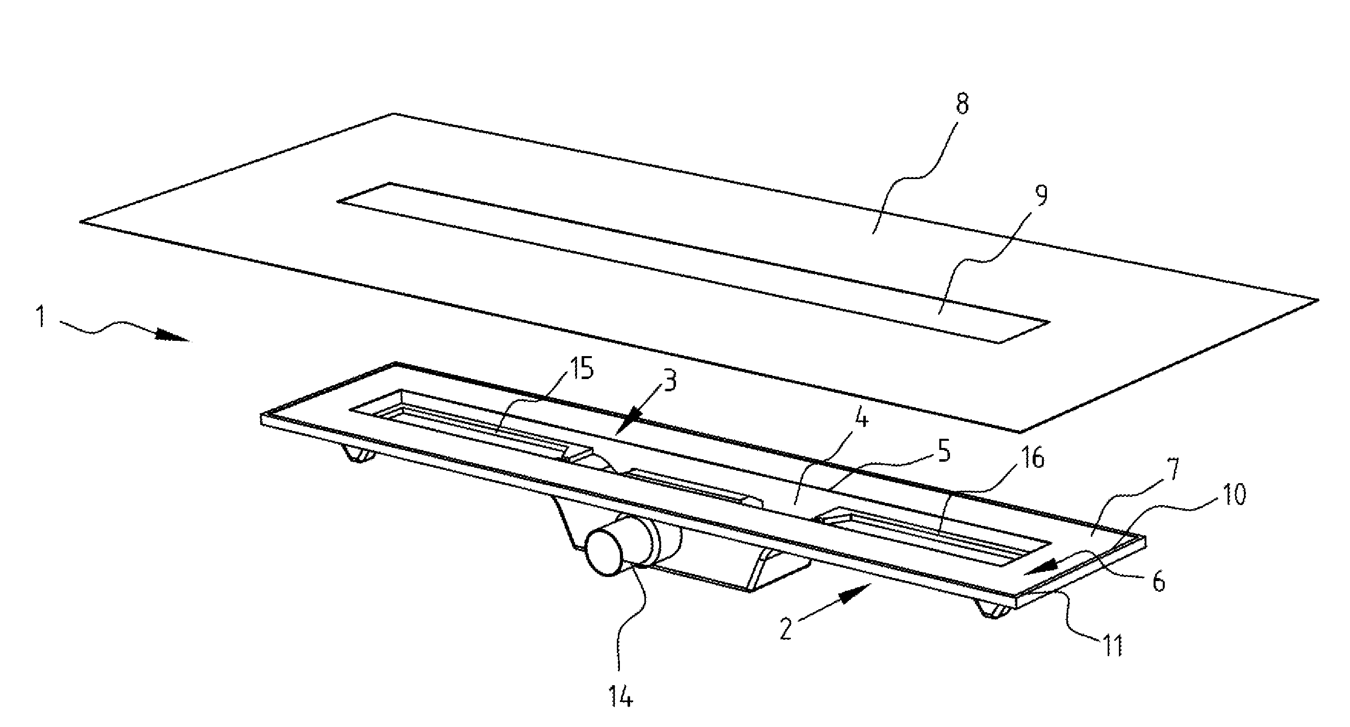
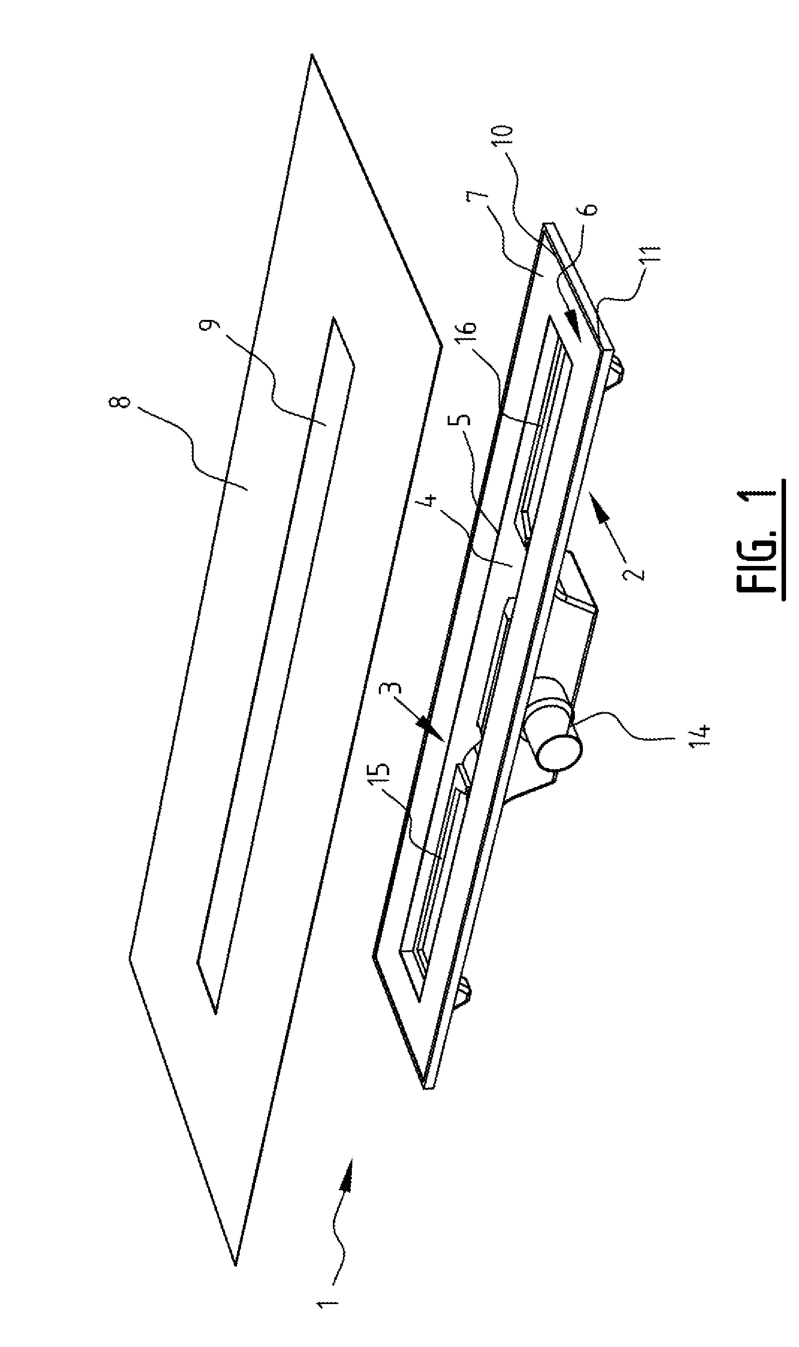
[0035]a drain assembly according to the invention will be illustrated hereinbelow with reference to FIGS. 1-5. The drain assembly comprises a drain body 1 with an upper side 3 and an underside 2. Drain body 1 is provided on its upper side 3 with an inlet zone 4 with a periphery 5. This periphery 5 transposes into a substantially horizontally extending peripheral flange 6. Underside 3 of drain body 1 is preferably intended to be arranged directly into a floor material such as mortar. The underside of peripheral flange 6 is thus placed directly against the floor material here, as will be further illustrated with reference to FIGS. 6A-D.

[0036]The drain body is preferably manufactured from a plastic which adheres to the typical floor materials such as mortar, and preferably from a mouldable plastic. It is however also possible to manufacture the drain body from metal. An example of a suitable material is a mouldable plastic on the basis of polyester resins and aluminium trihydrates. Suc...


PUM


Abstract

Methods and devices for drain assemblies including those for building into a floor. Such drain assemblies including a drain body which can be built into the floor and which has at the top an inlet zone with a periphery, a peripheral flange with an upper surface, extending substantially in a horizontal plane from this periphery, a water-sealing layer arranged adheringly on the upper surface of the peripheral flange, a sealing mat with the form of a frame with an inner periphery fitting around the periphery, wherein a portion of the sealing mat overlaps at least the outer periphery of the water-sealing layer, and wherein the sealing mat and the water-sealing layer are adapted to be water-sealing and to adhere well to tile adhesive.

Description

BACKGROUND[0001]1. Field of the Invention[0002]The present invention relates to a drain assembly, particularly for a walk-in shower, which drain assembly is intended for building into a tile floor. The invention further relates to a drain body for use in such an assembly and to a method for building-in of a drain.[0003]2. Description of the Related Art[0004]A known problem of the existing drains for tile floors is associated with making the connections between the drain and the tiles watertight. The development of drains typically takes place from the viewpoint of the plumber. Insufficient attention is paid here to the convenience of placing for a tiler.SUMMARY OF THE INVENTION[0005]The present invention has for its object to provide a drain assembly which can be placed easily and properly by a tiler and with which leakage and / or moisture problems can particularly be avoided.[0006]The invention relates for this purpose to a drain assembly which is distinguished in that it comprises ...

Claims


Application Information

Patent Timeline
Patent Type & Authority Applications(United States)
IPC IPC(8): E03C1/12
CPCE03F5/0408E03F2005/0413E03F5/0409
Inventor STEYLAERTS, PETER ROGER JOSEPHINASTEYLAERTS, PATRICK LEO ADRIAAN MARIA
Owner N V STEYLAERTS
Why Eureka
Try Eureka