Method for carrying out a self-test for a micromechanical sensor device, and corresponding micromechanical sensor device

Active Publication Date: 2011-03-24
ROBERT BOSCH GMBH
View PDF3 Cites 7 Cited by
  • Summary
  • Abstract
  • Description
  • Claims
  • Application Information

AI Technical Summary

Benefits of technology

[0009]The method according to the present invention for carrying out a self-test for a micromechanical sensor device and the corresponding micromechanical sensor device offer the advantage that they provide more robust self-test results compared to conventional approaches.
[0010]An essence of the present invention, therefore, lies in increased robustness of the self-test procedure and the self-test evaluation. The present invention provides that the results of at least two successive self-tests are compared to one another, correlated, or otherwise analyzed according to at least one predefined criterion, and on this basis the self-test result is established as a function of all self-test sequences.
[0011]For example, the present invention provides repetition of the self-test using a varied frequency or a varied period. In the evaluation it is no longer every single test signal that is individually evaluated, but, rather, variables which are additionally or exclusively derived from multiple tests, for example the mean value of all response signal values, or of specific positive, or all negative, response signal values. The self-test evaluation is thus made more stable with respect to external interferences of most varied amplitudes and frequencies. Also, in particular in sensors which are highly sensitive, this concept allows self-tests to be carried out and evaluated despite external interferences. The method according to the present invention is distinguished in that it requires only very slight use of resources in the controller and in the sensor.

Problems solved by technology

The sensor response to the self-test stimulus may be distorted externally or even completely overridden by interferences of the measured value.
An evaluation of the sensor response with respect to stored values may then erroneously result in an unsatisfactory outcome.
In sensors which automatically control the self-test and in which the self-test is not controlled by a controller, complex algorithms for controlling the self-test are not possible as a result of the limited computation resources, so that simple algorithms are used despite the described shortcoming.

Method used


Image

  • Method for carrying out a self-test for a micromechanical sensor device, and corresponding micromechanical sensor device
  • Method for carrying out a self-test for a micromechanical sensor device, and corresponding micromechanical sensor device
  • Method for carrying out a self-test for a micromechanical sensor device, and corresponding micromechanical sensor device

Examples


Embodiment Construction

[0019]Identical or functionally equivalent elements are denoted by the same reference numerals in the figures.

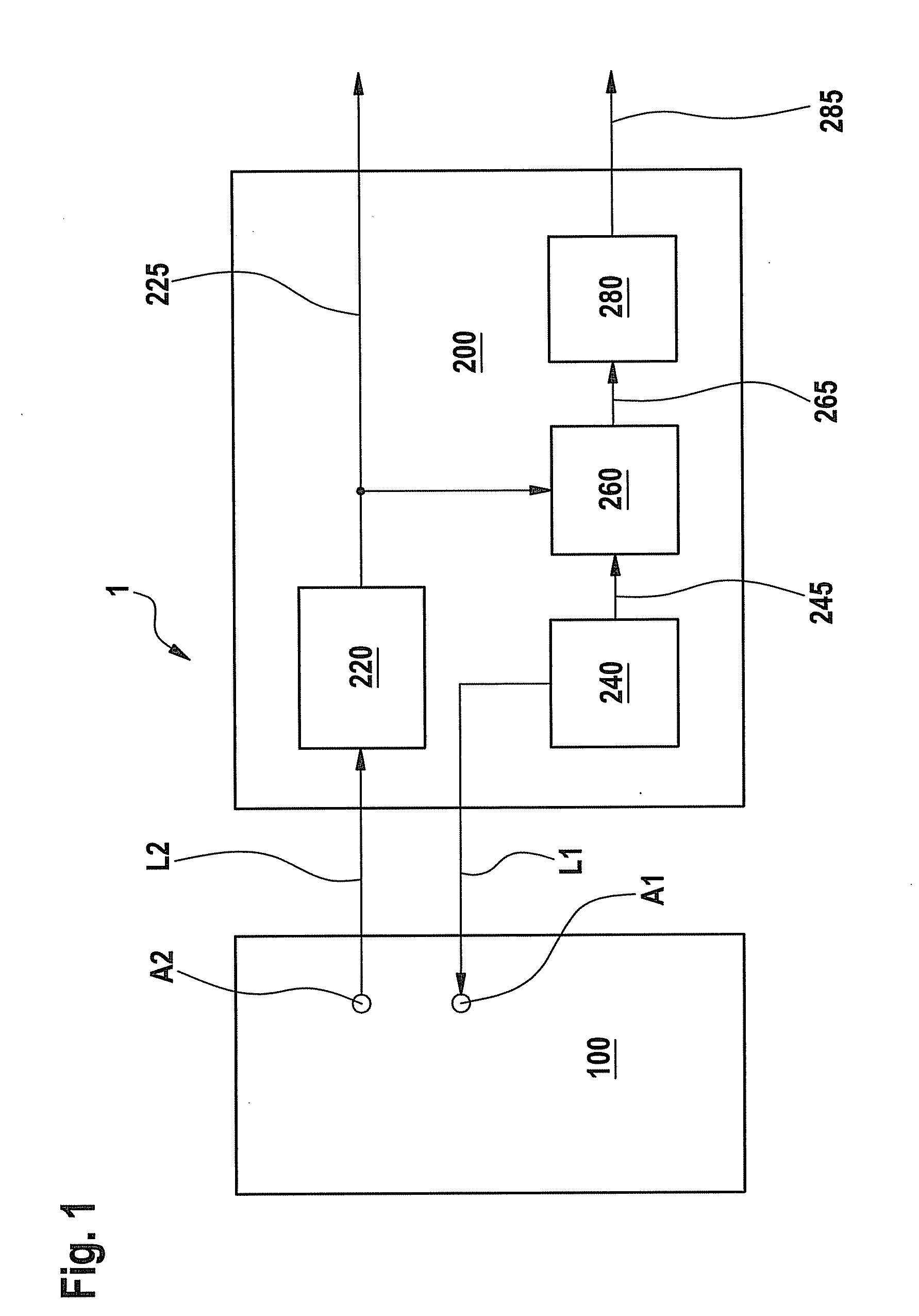
[0020]FIG. 1 shows a block diagram of a micromechanical sensor device according to one specific embodiment of the present invention.

[0021]In FIG. 1, reference numeral 1 denotes a micromechanical sensor unit having a micromechanical function portion 100 and an electronic evaluation circuit 200 which are electrically connected to one another via electrical lines L1, L2, respectively, the corresponding connecting points on the micromechanical function portion 100 being denoted by A1 and A2 and formed by bonding lands, for example.

[0022]Electronic evaluation circuit 200 includes an evaluation module 220, an excitation module 240, a demodulation module 260, and an assessment module 280.

[0023]Evaluation module 220 is used for evaluating the sensor signals during actual operation of the sensor, and also for evaluating the sensor signals in self-test mode, and delivers a sensor outp...


PUM


Abstract

A method for carrying out a self-test for a micromechanical sensor device, and a corresponding micromechanical sensor device. The method has the following steps: exciting the sensor device using a first excitation signal variation in a first self-test; storing a corresponding first response signal variation of the sensor device; exciting the sensor device using a second excitation signal variation in a second self-test; storing a corresponding second response signal variation of the sensor device; analyzing the first and second response signal variations with regard to at least one predefined criterion; and preparing a self-test result based on the analytical result of the first and second response signal variations.

Description

BACKGROUND INFORMATION[0001]In the use of micromechanical sensors, self-testing concepts are frequently employed to test the micromechanical system as well as the complete signal path of the sensors. Tests based on such self-testing concepts may involve, for example, application of an electrical stimulus to the micromechanical element and measurement of the response by the sensor. The measured signal or a variable derived therefrom is compared to target values and evaluated. The target values may be documented in writing (in technical customer specification sheets, for example) or stored in the sensor itself. The self-test per se is usually composed of a sequence of stimuli, for example a positive voltage excursion, a zero excursion (no self-test stimulus), and a negative voltage excursion, or the like.[0002]There are various ways to initiate self-tests and evaluate the corresponding sensor response to the self-test stimulus.[0003]For certain sensors, the self-test is externally con...

Claims


Application Information

Patent Timeline
IPC IPC(8): G01D21/00
CPCG01D18/00B81C99/0045G01D2218/10
Inventor KIMMERLE, STEFANBAUS, MICHAEL
Owner ROBERT BOSCH GMBH
Why Eureka
Try Eureka