Method and system for finding a manpads launcher position

a launcher position and launcher technology, applied in the field of countermeasures, can solve the problem of no continuous surveillance at an intrusive level of resolution, and achieve the effect of reducing the probability of a successful attack

Active Publication Date: 2011-03-24
BAE SYST INFORMATION & ELECTRONICS SYST INTERGRATION INC
View PDF11 Cites 26 Cited by
  • Summary
  • Abstract
  • Description
  • Claims
  • Application Information

AI Technical Summary

Benefits of technology

[0032]c) It enables wider use of on-aircraft countermeasures redu

Problems solved by technology

This is because there is no continuous surve

Method used


Image

  • Method and system for finding a manpads launcher position
  • Method and system for finding a manpads launcher position
  • Method and system for finding a manpads launcher position

Examples


Embodiment Construction

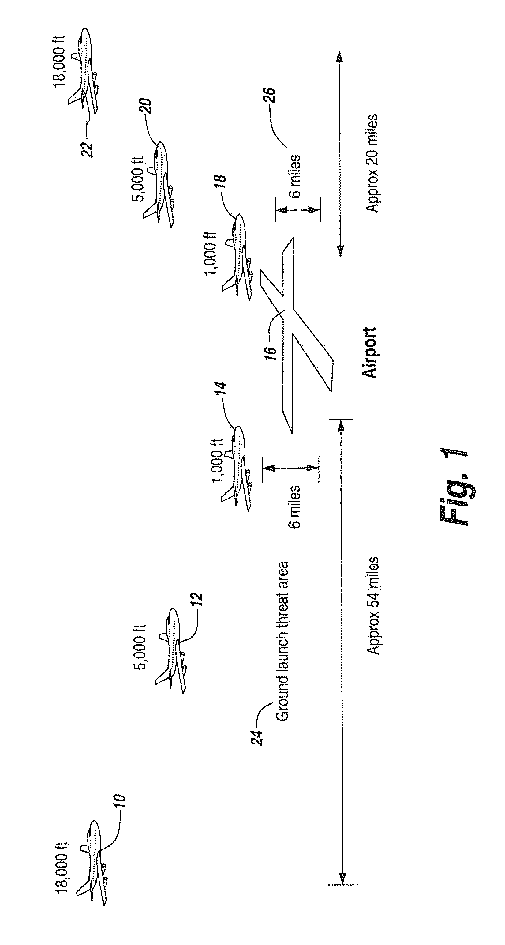
[0040]The counter terror network involved in the subject invention includes a set of sensing and observing nodes distributed over take off and landing regions of airports capable of handling wide body commercial aircraft. FIG. 1 shows the scope of the area which has to be monitored in the event of a notification of an attack. This area corresponds to the runway in use. Many large airports have several runways to enable them to operate under varied wind conditions, each having a corresponding runway to be monitored. In FIG. 1 successive positions of an incoming aircraft are shown at10, 12 and 14. There is also an airport 16 and successive positions of an outgoing aircraft at 18, 20 and 22. Also shown is a ground launch threat area 24 for incoming aircraft that are landing, and a launch threat area 26 for outgoing aircraft that are taking off.

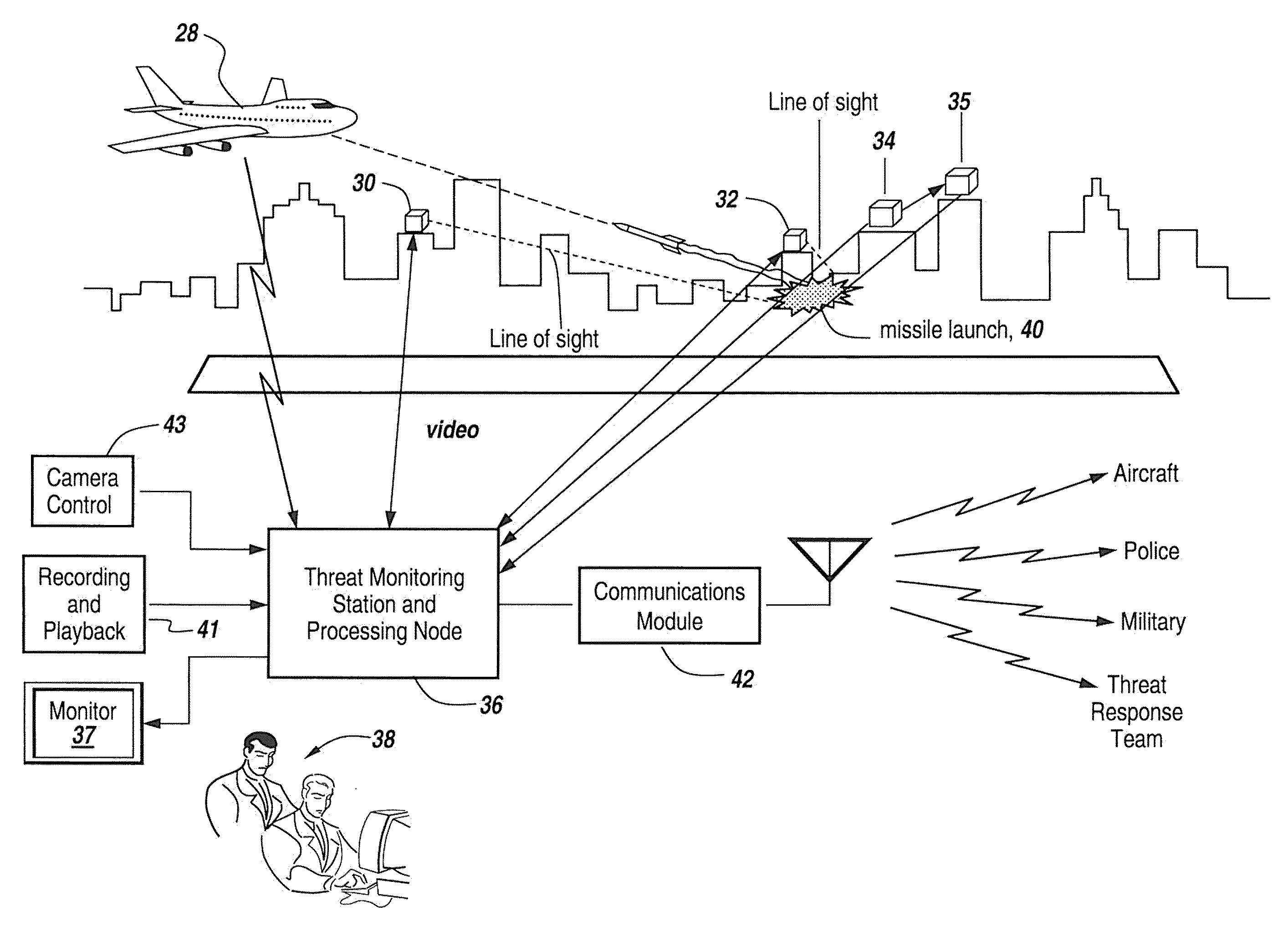
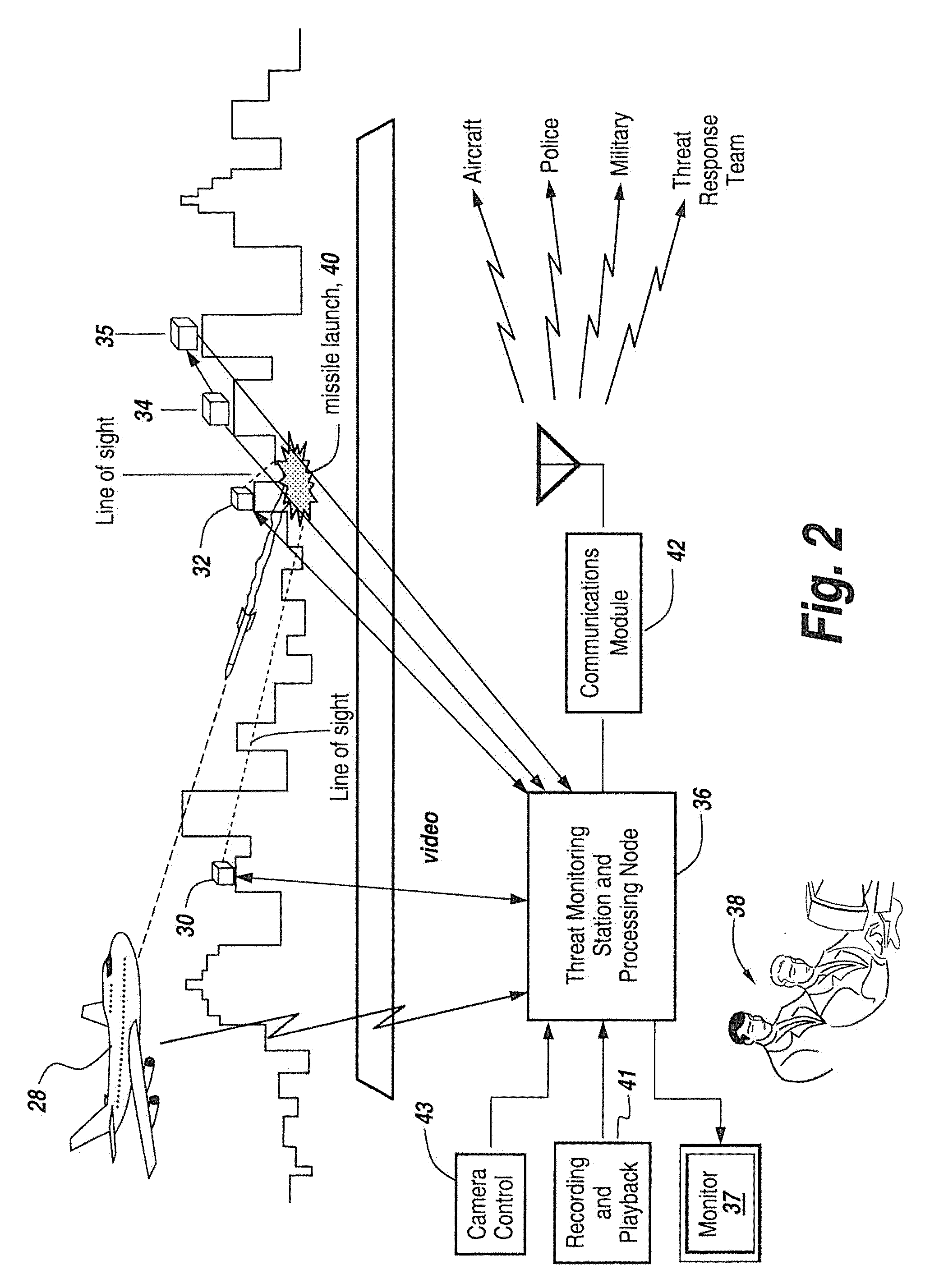
[0041]Referring to FIG. 2, what is shown is an incoming aircraft 28, two sensor nodes 30 and 32, a missile launch detector 34, an event localiza...


PUM


Abstract

A method for finding the launch of a ManPADS missile comprising the steps of installing a network of electro optical (EO) and infrared (IR) cameras with a triggering receiver and pointing the EO and IR cameras in the direction of a suspicious emission, wherein the EO camera provides high resolution video and the IR camera finds the ManPADS and tracks its user.

Description

RELATED APPLICATIONS[0001]This patent application claims rights under 35 USC §119(e) from Provisional Application Ser. No. 61 / 067,535 filed Feb. 28, 2008 entitled Method and System For Finding A ManPADS Launcher Position, the contents of which are incorporated herein by reference.FIELD OF THE INVENTION[0002]The present invention relates to countermeasures. More particularly the present invention relates to methods and systems for locating terrorists employing a Man Portable Air Defense System (ManPADS) or other weapons to confirm that a missile has been launched or that other weapons have been employed.BACKGROUND OF THE INVENTION[0003]ManPADS are shoulder fired infrared seeking guided missiles which are used against low flying aircraft. Some experts it the field of counter-terrorism have expressed opinions that ManPADS, if in the hands of terrorists, may pose a hazard to commercial airlines during take off or landing. The prior art has suggested installing devices on commercial airl...

Claims


Application Information

Patent Timeline
IPC IPC(8): H04N7/18H04N5/225
CPCG06T7/004G06T7/2093G06T2207/30196G06T2207/10036G06T2207/10048G06T2207/10021G06T7/292G06T7/70
Inventor WEBER, JONATHAN L.KRAVITZ, ARNOLD
Owner BAE SYST INFORMATION & ELECTRONICS SYST INTERGRATION INC
Why Eureka
Try Eureka