Flush Valve Hydrogenerator

a technology of flush valve and hydrogenerator, which is applied in the direction of wind motors with perpendicular air flow, mechanical power/torque control, optical radiation measurement, etc., can solve the problems of large loss of water flow energy, insufficient power generation using such a small hydrogenerating device, and inability to convert large amount of water flow energy into electrical energy, etc., to achieve efficient electrical power generation

Active Publication Date: 2011-03-24
ZURN INDS
View PDF100 Cites 22 Cited by
  • Summary
  • Abstract
  • Description
  • Claims
  • Application Information

AI Technical Summary

Benefits of technology

[0010]An object of the present invention is to provide an efficient hydrogenerator device for use with a flush valve or other plumbing fixture that directs substantially all of the water from a water inlet over the blades of a rotor to efficiently generate electrical power from the flow of water. It is a further object of the present invention to provide a control device for controlling the flush valve or other plumbing fixture using the electrical power generated by the hydrogenerator device.
[0011]The present invention is directed to a power generating device for use with a flush valve. The power generating device includes: a volute configured to receive water from a water supply pipe; a stator having a plurality of blades positioned around a circumference thereof positioned within the volute; a rotor positioned within the stator; and a generator coupled to the rotor. The volute directs substantially all of the water received from the water supply pipe in a circumferential direction through the plurality of blades of the stator to the rotor, thereby causing the rotor to rotate.
[0016]In addition, the present invention is directed to a control apparatus for a hydrogenerator flush valve. The control apparatus includes: an electric power generation device provided in a fluid path of the hydrogenerator flush valve; a load switch coupled between the electric power generation device and at least one supercapacitor; and a solenoid valve operationally coupled to the at least one supercapacitor and configured to allow water to flow into the hydrogenerator flush valve from a water supply pipe when in a first position and prevent water from flowing into the hydrogenerator flush valve from the water supply pipe when in a second position. The at least one supercapacitor is charged by the electric power generation device and power requirements of the solenoid valve are satisfied by the at least one supercapacitor. The load switch opens when the at least one supercapacitor is completely charged.

Problems solved by technology

Where the automatic plumbing fixture is installed in an existing building, installation of a power distribution panel and / or an electric cable can be costly, time consuming, and difficult.
However, it is difficult to generate enough power using such a small hydrogenerating device and small-scale water source.
Therefore, a large amount of the energy of the flowing water is lost and not converted into electrical energy.

Method used


Image

  • Flush Valve Hydrogenerator
  • Flush Valve Hydrogenerator
  • Flush Valve Hydrogenerator

Examples


Embodiment Construction

[0040]For purposes of the description hereinafter, the terms “upper”, “lower”, “right”, “left”, “vertical”, “horizontal”, “top”, “bottom”, “lateral”, “longitudinal”, and derivatives thereof shall relate to the invention as it is oriented in the drawing figures. However, it is to be understood that the invention may assume alternative variations and step sequences, except where expressly specified to the contrary. It is also to be understood that the specific devices and processes illustrated in the attached drawings, and described in the following specification, are simply exemplary embodiments of the invention. Hence, specific dimensions and other physical characteristics related to the embodiments disclosed herein are not to be considered as limiting.

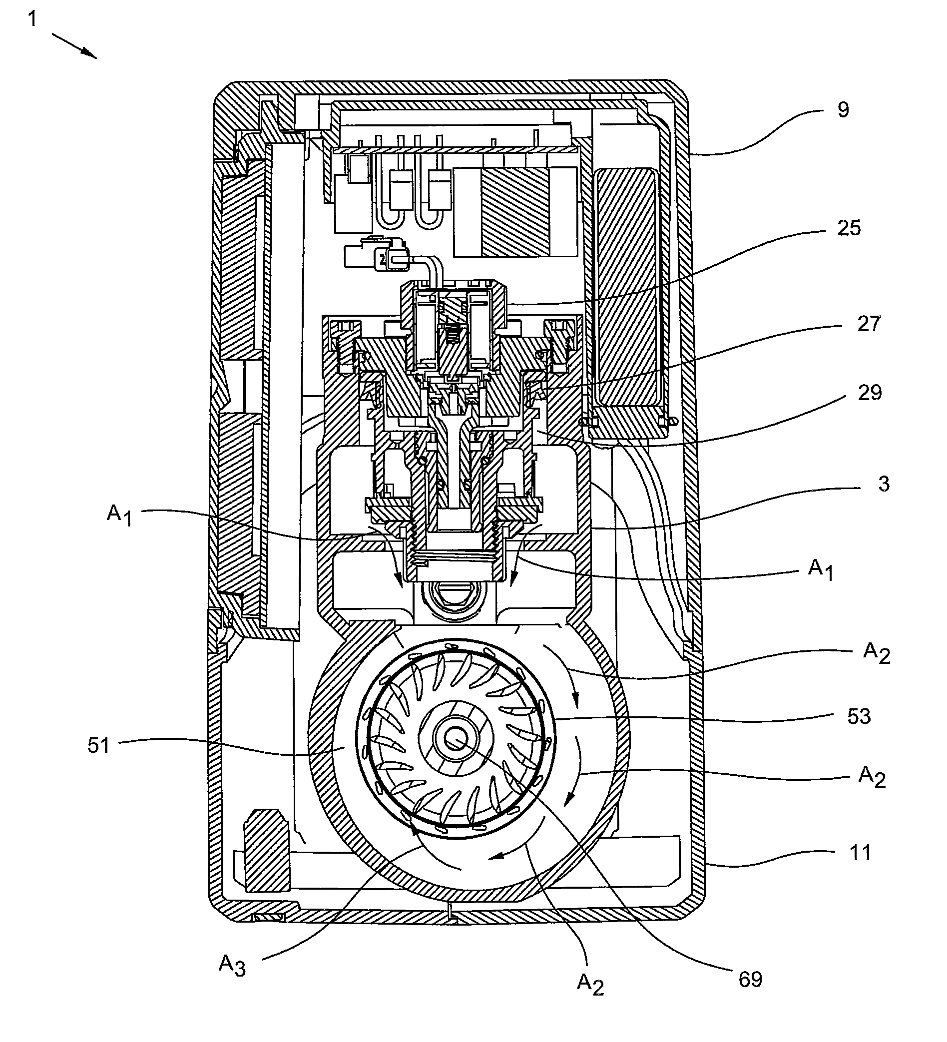
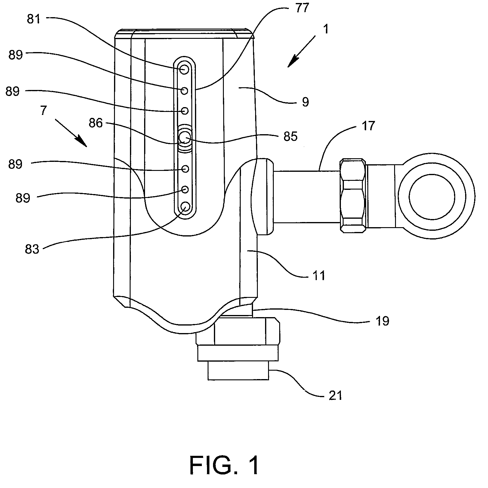
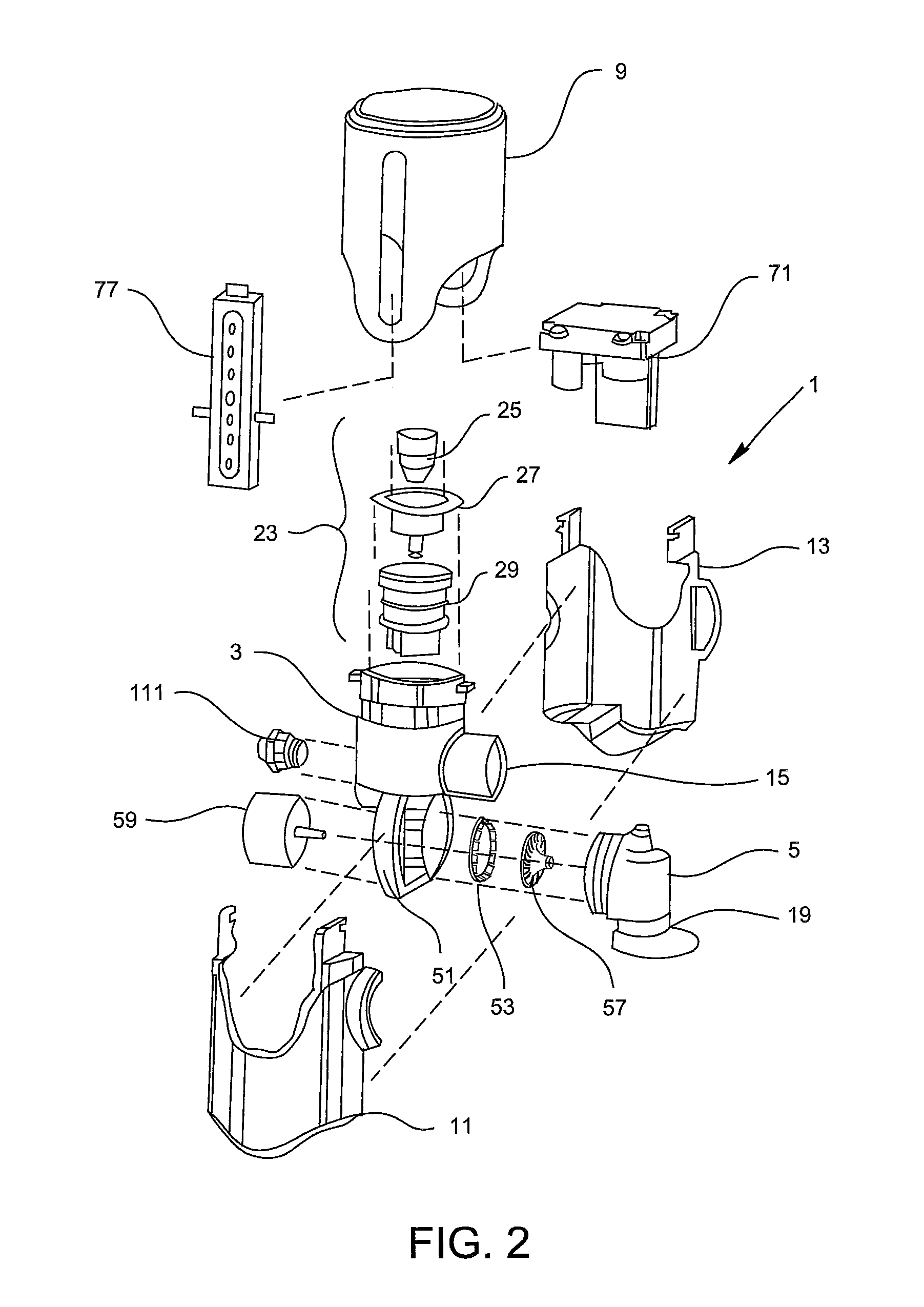
[0041]With reference to FIGS. 1 and 2, a hydrogenerator flush valve, generally denoted as reference numeral 1, includes a primary valve casing 3 and a secondary valve casing 5 disposed within a housing, generally denoted as reference ...


PUM


Abstract

A power generating device for use with a plumbing fixture includes: a volute configured to receive water from a water supply pipe; a stator having a plurality of blades positioned around a circumference thereof positioned within the volute; a rotor positioned within the stator; and a generator coupled to the rotor. The volute directs substantially all of the water received from the water supply pipe in a circumferential direction through the plurality of blades of the stator to the rotor, thereby causing the rotor to rotate.

Description

CROSS REFERENCE TO RELATED APPLICATIONS[0001]This application claims priority to U.S. Provisional Patent Application Ser. No. 61 / 244,970 entitled “Flush Valve Hydrogenerator” filed Sep. 23, 2009, the entire disclosure of which is hereby incorporated by reference in its entirety.BACKGROUND OF THE INVENTION[0002]1. Field of the Invention[0003]The present invention is generally related to flush valves for water closets, urinals, and the like and, more specifically, to an electric power generation device for use with such a flush valve.[0004]2. Description of Related Art[0005]Hydroelectric power generation in which kinetic energy is extracted from flowing pressurized water and used to rotate a generator to produce electric power is known. With large hydroelectric power generation operated with a large-scale water source such as a river or dam, thousands of megawatts of power may be generated using millions of gallons of flowing water. As such, conversion of the kinetic energy in the flo...

Claims


Application Information

Patent Timeline
Patent Type & Authority Applications(United States)
IPC IPC(8): H02P9/02F03B3/16F04D25/10H02K7/18G06F1/32G01J1/44
CPCF03B13/00F05B2220/60F05B2220/602H02P2101/10H02P9/04Y02B10/50H02K7/1823Y02E10/20
Inventor GLASSER, JAMIEGRACE, SCOTTJONES, STEVEN R.SCHOOLCRAFT, JOHN KEVINHILL, ROBERTBARTEE, JOHNBLACKMON, III, ZACK
Owner ZURN INDS
Why Eureka
Try Eureka