Connecting device for a frame structure

Inactive Publication Date: 2011-03-31
HILTI AG
View PDF7 Cites 5 Cited by
  • Summary
  • Abstract
  • Description
  • Claims
  • Application Information

AI Technical Summary

Benefits of technology

[0021]The first feed-through opening for the at least one clamping device in the support section of the base element is preferably configured as an elongated hole, thereby guaranteeing a simple adjustability of the connecting device and the crossbar accommodated therein. The first feed-through opening is preferably configured as a curved elongated hole, wherein the radius of the elongated hole corresponds to the distance of the elongated hole from the second feed-through opening in the base element and the concave longitudinal side of the elongated hole is facing this feed-through opening. When the connecting element is in a loosened state, the receptacle element can be swiveled around a swivel axis formed by the at least one bearing device relative to the base element.
[0022]One of the feed-through openings preferably has a threaded section for a thread arranged on at least one clamping device and/or for a thread arranged on at least one bearing device, whereby it is possible to dispense with additionally arranged clamping elements, such as, for example, nuts, for clamping the at least one clamping device and/or the at least one bearing device. As a result, the connecting device has substantially fewer individual parts, thereby ma

Problems solved by technology

For anchorage in the substrate, the support profiles are often rammed into or screwed into the substrate so that a perpendicular alignment is not always guaranteed after driving in the same.
The disadva

Method used


Image

  • Connecting device for a frame structure
  • Connecting device for a frame structure
  • Connecting device for a frame structure

Examples


Example

DETAILED DESCRIPTION OF THE DRAWINGS

[0032]As a rule, the same parts are provided with the same reference numbers in the figures.

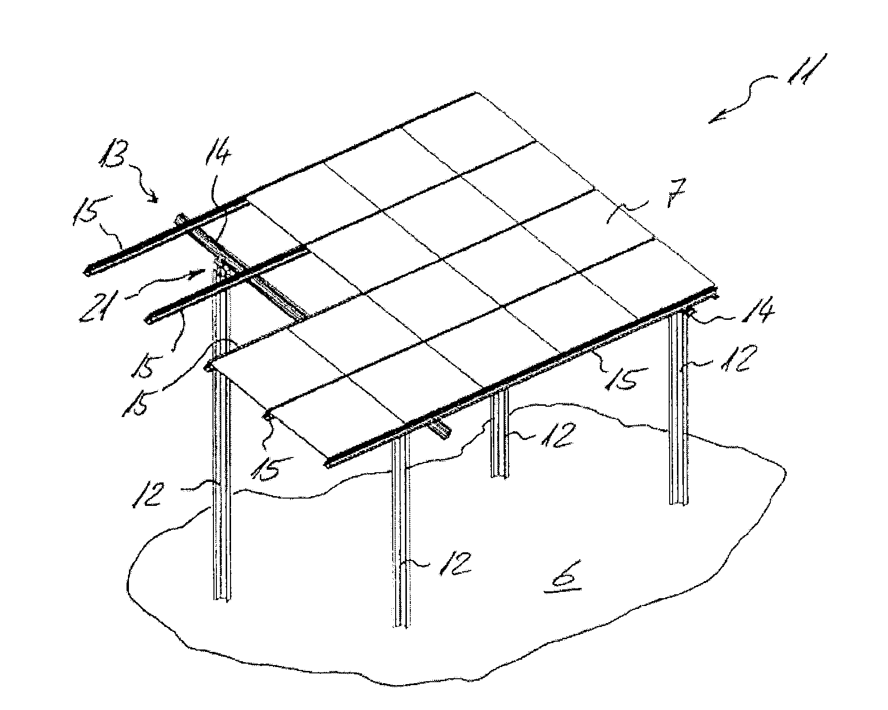
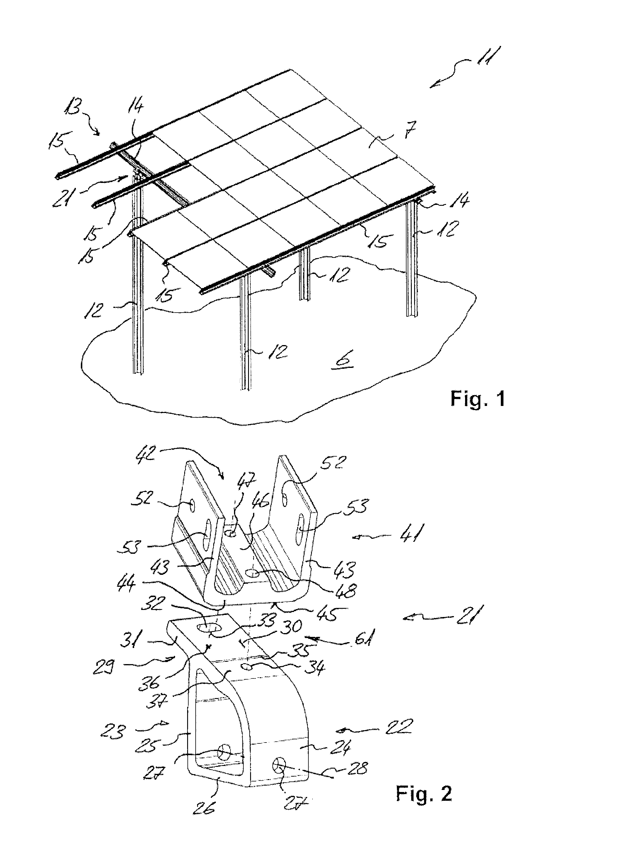
[0033]The frame structure 11 for solar panels 7 depicted in FIG. 1 has several support profiles 12 rammed into the substrate as well as a grid 13 of several transverse crossbars 14, which run from support profile 12 to support profile 12, and of several longitudinal crossbars 15, which are arranged crosswise from the transverse crossbars 14. A connecting device 21 is respectively provided between the support profiles 12 and the transverse crossbars 14.

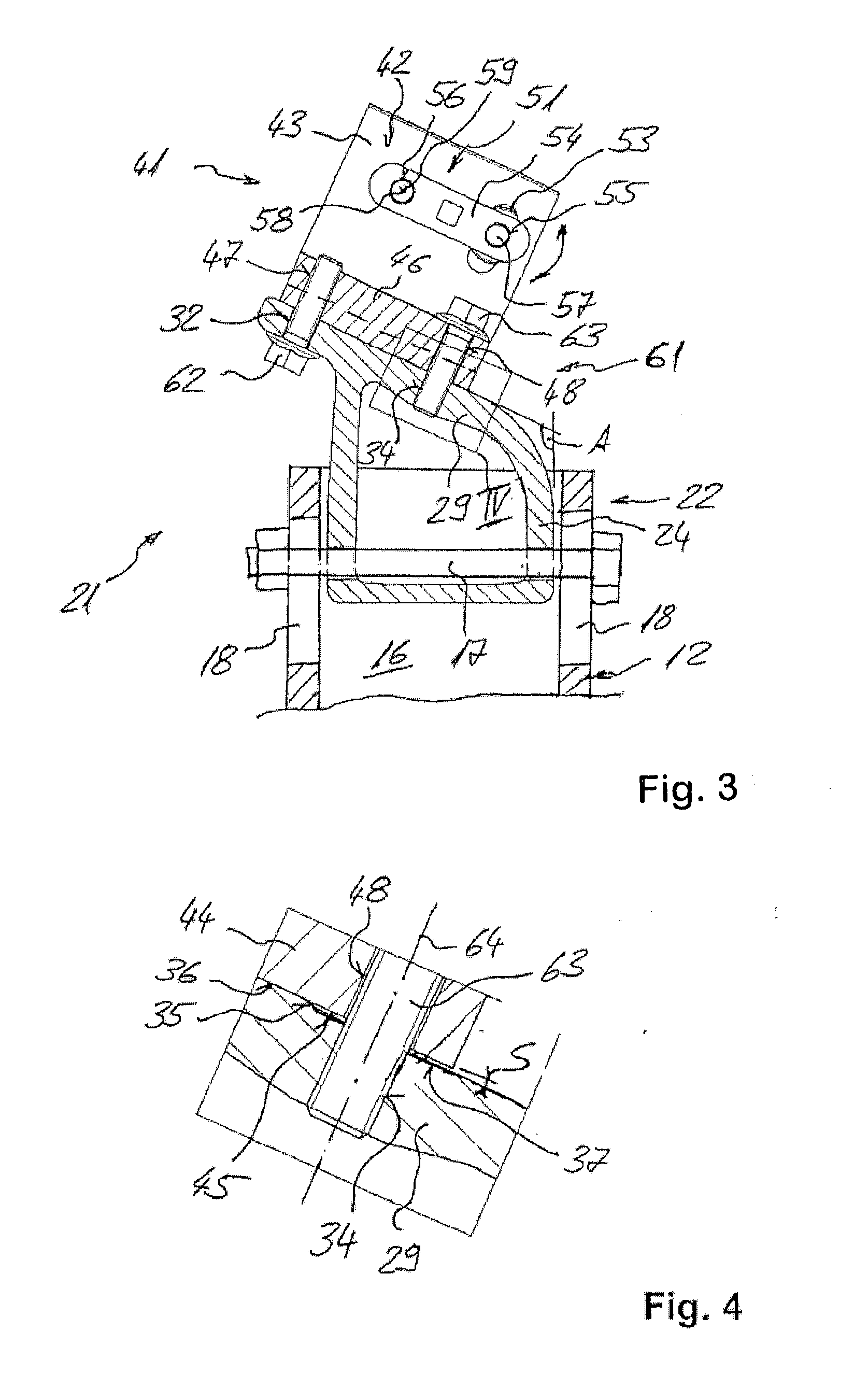
[0034]The connecting device 21 shown in detail in FIGS. 2 to 4 has a base element 22 and a receptacle element 41, which can be fixed by means of a locking device 61 relative to the base element 22 on the base element.

[0035]The base element 22 has a fastening section 23 for arrangement on a support profile 12 of the frame structure 11, which is formed by two side walls 24 and 25 running parallel to one another ...


PUM


Abstract

A connecting device for a frame structure made of support profiles and crossbars for the arrangement of solar panels, as well as a frame structure with a connecting device, is disclosed. The connecting device has a base element, a receptacle element, and a locking device by which the receptacle element can be fixed relative to the base element on the base element. The base element has a fastening section as well as a support section with a support side facing the receptacle element. The receptacle element has a receptacle for a crossbar of the frame structure as well as an application section with an application side facing the base element. The locking device has a clamping device as well as a bearing device. An application area and at least one depression area are provided between the clamping device and the bearing device.

Description

[0001]This application claims the priority of German Patent Document No. 10 2009 045 209.5, filed Sep. 30, 2009, the disclosure of which is expressly incorporated by reference herein.BACKGROUND AND SUMMARY OF THE INVENTION[0002]The invention relates to a connecting device for a frame structure made of support profiles and of crossbars, in particular for the arrangement of solar panels. The invention also relates to a frame structure, in particular for the arrangement of solar panels with such a connecting device.[0003]A frame structure has support profiles anchored in or on a substrate, e.g., in the ground, on which a grid of crossbars arranged lengthwise and crosswise is provided as a supporting frame. Plate-like elements, such as solar panels, are arranged on the crossbars in the desired alignment. The crossbars are, for example, assembly rails, which can be connected with one another simply via appropriately configured fastening devices and on which the plate-like elements can be...

Claims


Application Information

Patent Timeline
IPC IPC(8): E04H12/34
CPCE04B2001/2415E04B2001/2439F24J2/5232Y02E10/47F24J2/526F24J2/5264F24J2/5233F24S25/65F24S25/12F24S25/70
Inventor KEMPLE, LORCANMUNDWILER, LUKAS
Owner HILTI AG
Why Eureka
Try Eureka