

Flooring apparatus and systems for improved reduction of impact forces during a fall
a technology for flooring and impact force reduction, applied in the field of flooring apparatus, can solve the problems of non-fatal injuries, situation presenting significant health problems, relatively large deflection of mats, etc., and achieve the effect of increasing optimizing the stiffness of columns
- Summary
- Abstract
- Description
- Claims
- Application Information
AI Technical Summary
Benefits of technology
Problems solved by technology
Method used
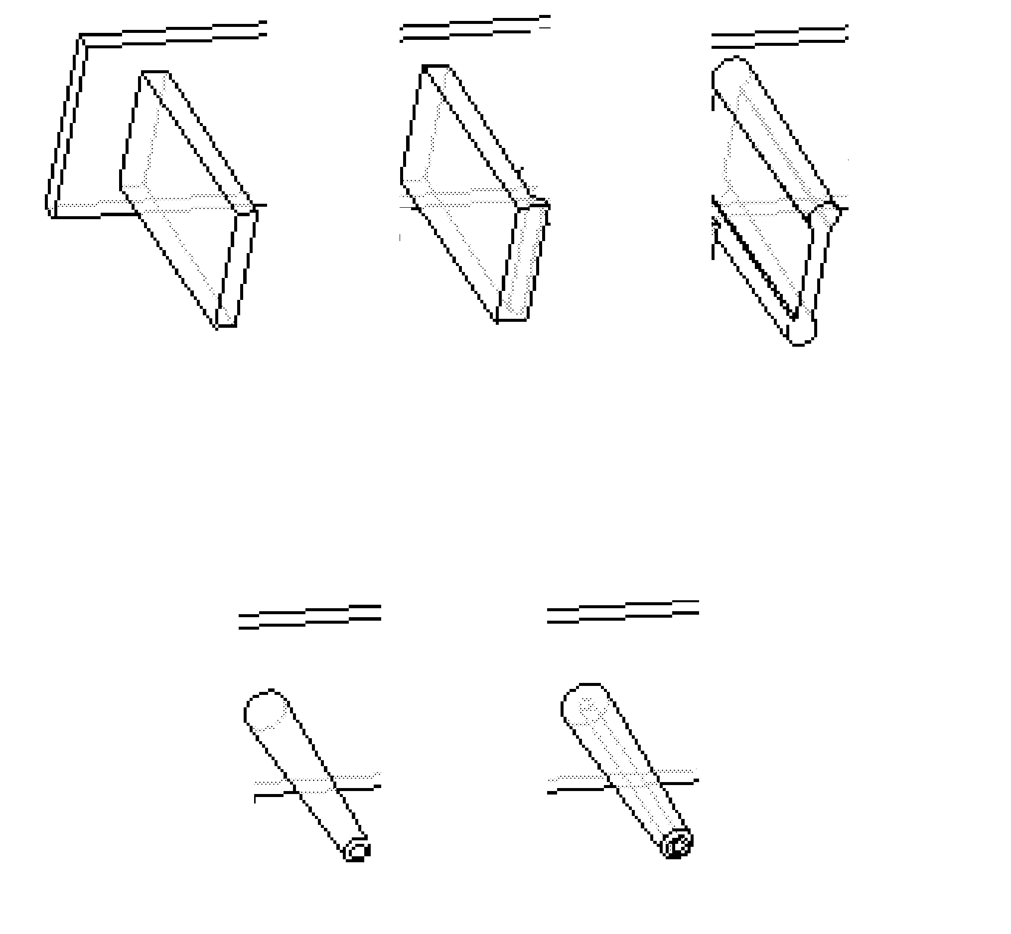
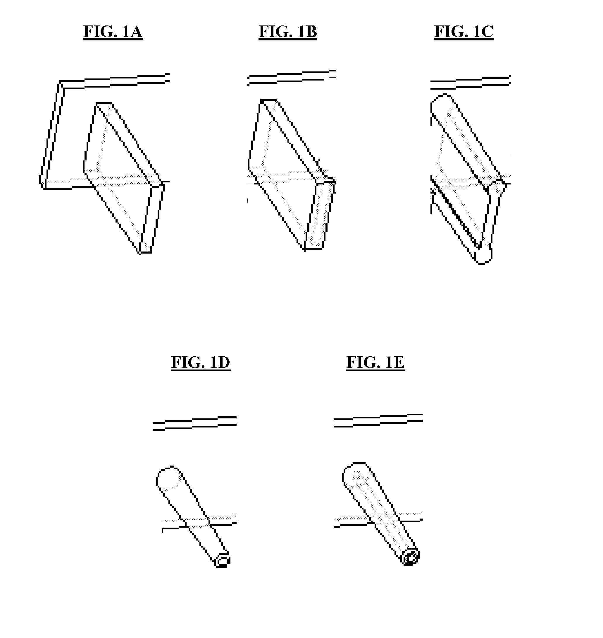
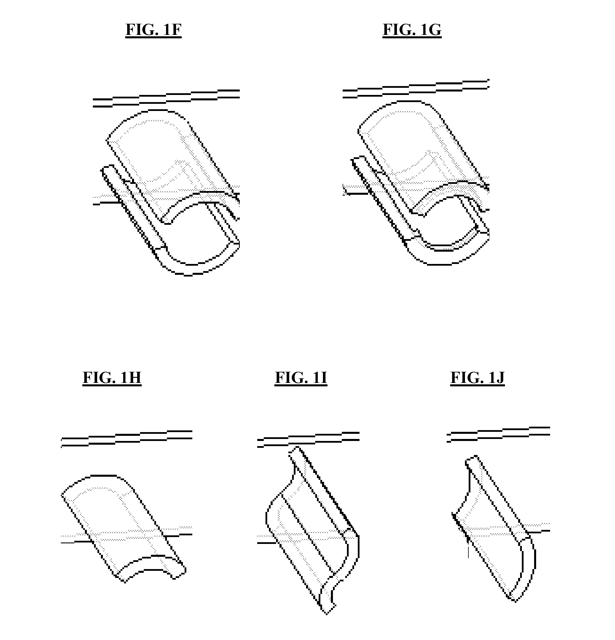
Image

Examples
example 1
[0121]In this example, a flooring apparatus is fabricated in accordance with embodiments of the invention (utilizing a matrix material). A section (tile) of the flooring apparatus is subjected to static load-deflection testing using a standard 3.5-inch-diameter metal load cylinder. FIG. 2 shows experimental static load-deflection curves for three different locations, demonstrating critical dynamic buckling pressures of about 30 psi to about 40 psi.
example 2
[0122]In this example, two flooring apparatus are fabricated in accordance with embodiments of the invention (both utilizing matrix materials). A section (tile) of each flooring apparatus is subjected to static load-deflection testing using a standard 3.5-inch-diameter metal load cylinder. FIG. 3 shows experimental static load-deflection curves for two different samples, demonstrating a critical dynamic buckling pressures of 37 psi for Sample 1 and 29 psi for Sample 2.
example 3
[0123]A standard polyurethane foam and a viscoelastic polyurethane foam, as possible matrix materials, are subjected to force-compression measurements. FIG. 4 shows experimental force-compression curves for these two different materials during loading and unloading.
PUM
| Property | Measurement | Unit |
|---|---|---|
| critical dynamic buckling pressure | aaaaa | aaaaa |
| static buckling pressure | aaaaa | aaaaa |
| density | aaaaa | aaaaa |
Abstract
Description
Claims
Application Information