
Drive device for driving first and second lift rotors of a rotorcraft having twin rotors in tandem

a technology of rotorcraft and drive device, which is applied in the direction of propellers, seating furniture, water-acting propulsive elements, etc., can solve the problems of rotorcraft being destroyed, rotorcraft being subjected to a high level of yaw, and it is difficult to keep the rotors far enough apart to avoid any inciden

Inactive Publication Date: 2013-03-12
EUROCOPTER
View PDF10 Cites 0 Cited by
  • Summary
  • Abstract
  • Description
  • Claims
  • Application Information

AI Technical Summary

Benefits of technology

The present invention aims to solve the issues related to previous solutions for rotorcraft with twin rotors while ensuring safety, reliability, and performance. The invention offers a novel approach by using two transmission shafts that are better designed for the specific configuration of the rotorcraft. This allows for better optimization of the weight and size of the shafts, making them easier to adapt to the configuration of the rotorcraft. The invention also provides a larger number of segments when using a shaft of the subcritical type. Additionally, the invention includes a step-down gear arrangement that optimizes the stiffness of the assembly. Overall, the invention enables a safer, reliable, and performance-oriented rotorcraft with twin rotors to be certified for civil use.

Problems solved by technology

Nevertheless, while it is rotating, a rotor driven by a gearbox subjects the rotorcraft to a high level of torque in yaw.
If the rotors are not spaced far enough apart from each other, then the blades of the first rotor might collide with the blades of the second rotor, thereby causing them to be destroyed, and consequently causing the rotorcraft to be destroyed.
Nevertheless, in practice, it is very difficult to keep the rotors far enough apart to avoid any incident.
Nevertheless, since the rotor disks can be inclined in order to maneuver the rotorcraft, it is practically impossible to offset the first and second rotors far enough apart vertically to avoid any risk of interference between their blades.
Nevertheless, should the transmission shaft break, then at least one rotor would no longer be driven, and that would lead to an accident for the rotorcraft.
Furthermore, if the engine is stopped, the drive system is no longer driven, and that also can lead to an accident for the rotorcraft.
Nevertheless, the above-mentioned drawbacks would seem to persist with that second solution.
In spite of the above-mentioned drawbacks, the use of a single transmission shaft does not make it possible to comply with the certification objectives that are required by the organizations that issue airworthiness certificates for civil aircraft.
Furthermore, since the distance between the first and second rotors can be large, that third solution requires a large number of gears, which can be very penalizing in terms of the weight and the reliability of the rotorcraft, given the large number of components.

Method used


Image

  • Drive device for driving first and second lift rotors of a rotorcraft having twin rotors in tandem
  • Drive device for driving first and second lift rotors of a rotorcraft having twin rotors in tandem
  • Drive device for driving first and second lift rotors of a rotorcraft having twin rotors in tandem

Examples


first embodiment

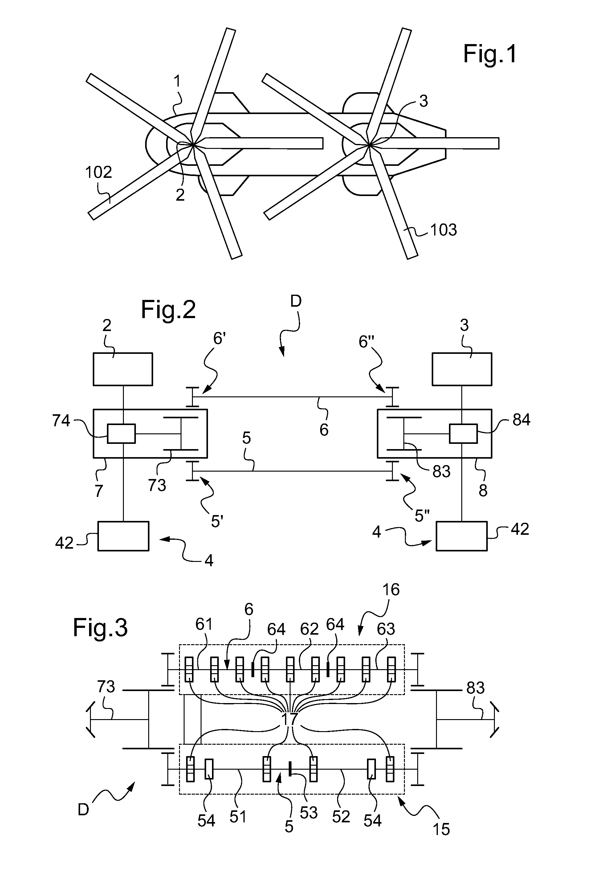
[0076]Consequently, with reference to FIG. 3, and in a first embodiment, the drive device D has first and second retaining means 15 and 16 respectively for retaining the first and second transmission shafts 5 and 6.

[0077]Each of the first and second retaining means 15 and 16 comprises a plurality of bearings 17. Since the bearings are distributed longitudinally along each of the first and second transmission shafts 5 and 6, these bearings are in a position to guide the first and second transmission shafts 5 and 6 in rotation, even in the event of failure, so as to contain said shafts within a predefined volume.

[0078]It should be observed that FIG. 3 shows a first transmission shaft 5 of the supercritical type.

[0079]This supercritical first transmission shaft 5 comprises two segments 51 and 52 that are connected together by conventional means 53.

[0080]Each segment of the first transmission shaft 5 is then provided with two bearings 17 and with a damper 54.

[0081]In contrast, the secon...

second embodiment

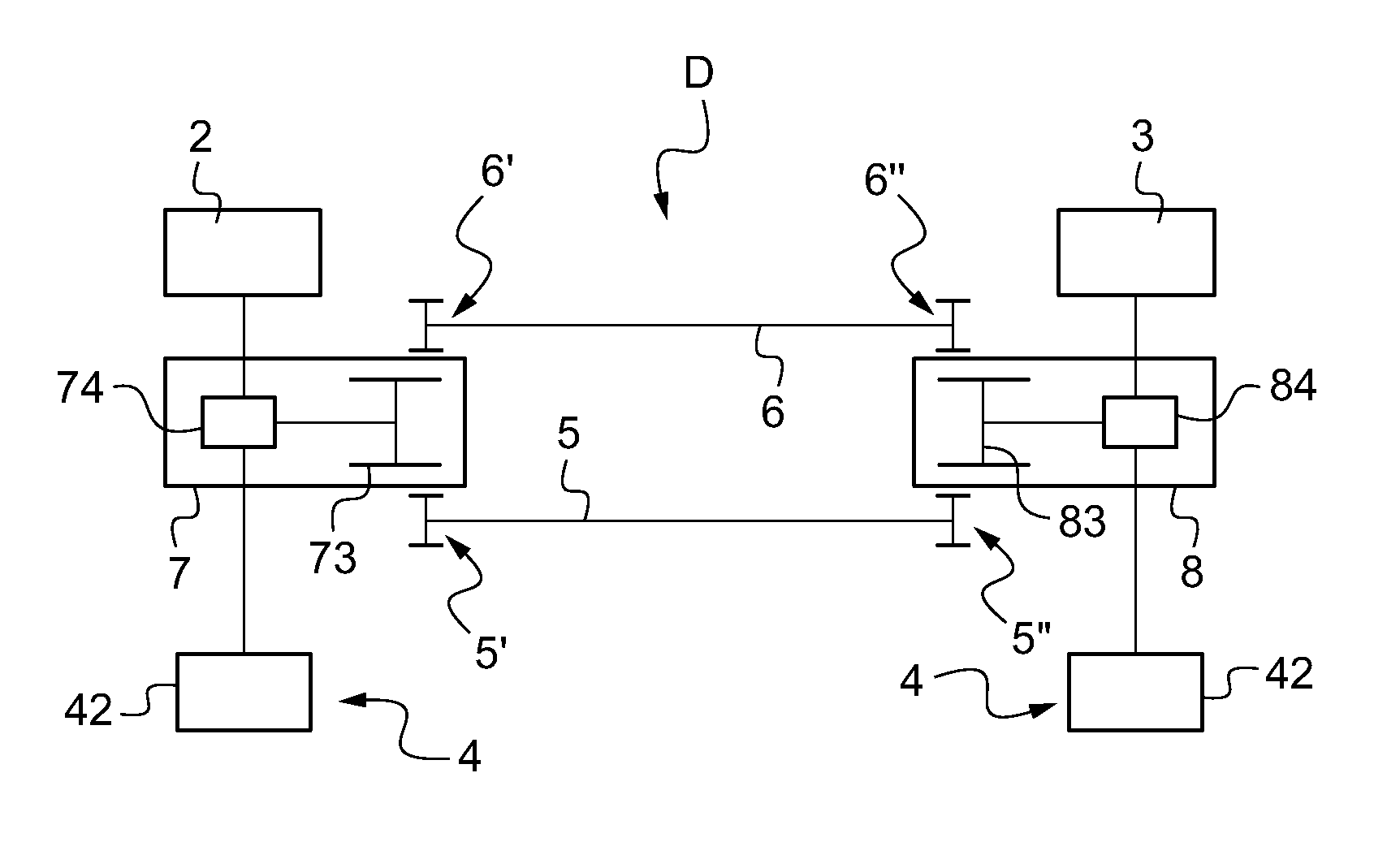
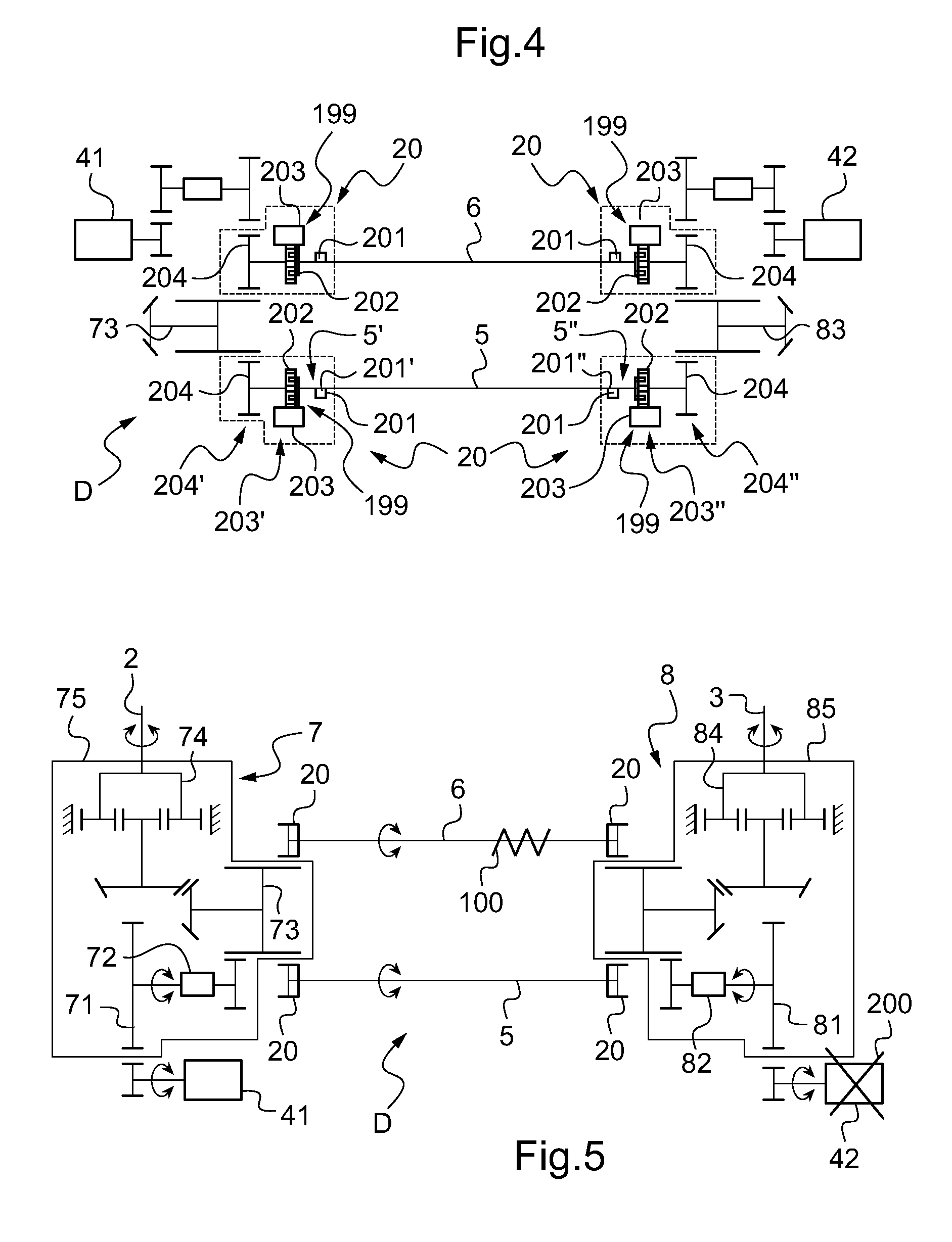
[0083]With reference to FIG. 4, in a second embodiment, at least one emergency decoupling system 20 is implemented.

[0084]Thus, a respective emergency decoupling system 20 is arranged between each transmission shaft 5 or 6 and each of the power combiner means 73 and 83. In the event of one of the transmission shafts failing, each emergency decoupling system 20 enables the failed transmission shaft to be disconnected from one of the power combiner means 73 and 83.

[0085]Each emergency decoupling system 20 then comprises a mechanical assembly 199 provided with break detector means 201 for detecting breakage of the associated transmission shaft, with a shape-interference coupling 202, with control means 203, and with a link shaft 204.

[0086]In the event of one of the transmission shafts breaking, the transmission shaft will flap and generate undue vibration. The detector means 201 detects this vibration and sends a signal to the control means 203 that order the shape-interference coupling...


PUM


Abstract

A drive device (D) for driving first and second lift rotors (2, 3) of a twin-rotor rotorcraft, includes link elements provided with first and second transmission shafts (5, 6) for synchronizing the first and second transmission members (74, 84) of first and second main gearboxes (7, 8), the first main gearbox (7) being provided with first power combiner element (73) firstly meshing with the first transmission member (74) and secondly mechanically linked with the first transmission shaft (5) and with the second transmission shaft (6), and the second main gearbox (8) being provided with second power combiner element (83) firstly meshing with the second transmission member (84), and secondly mechanically linked with the first transmission shaft (5) and with the second transmission shaft (6).

Description

FIELD OF THE INVENTION[0001]The present invention relates to a drive device for driving first and second lift rotors of a rotorcraft having twin rotors in tandem.BACKGROUND OF THE INVENTION[0002]An aircraft may be fitted with two lift rotors that provide it both with lift and with propulsion. In a rotorcraft, these two rotors may be arranged one behind the other along the longitudinal axis of said rotorcraft: this is referred to as a rotorcraft having twin rotors in tandem. Conventionally, each rotor of a twin-rotor rotorcraft is driven by a respective main gearbox (MGB). The main gearboxes, driven by an appropriate power plant, serve to reduce the speed of rotation between a power source and a rotor by a ratio of the order of 10 to 100.[0003]Each rotor comprises a plurality of blades secured to a hub and enabling the rotorcraft to be provided with lift and propulsion. Nevertheless, while it is rotating, a rotor driven by a gearbox subjects the rotorcraft to a high level of torque i...

Claims


Application Information

Patent Timeline
Patent Type & Authority Patents(United States)
IPC IPC(8): B64C11/50B64C27/08B64C27/14
CPCB64C27/08B64C27/12B64C27/14
Inventor THOMASSEY, LIONELMAGRE, ERIC
Owner EUROCOPTER
Learn More