Power unit for a vehicle

a technology for power units and vehicles, applied in the direction of gearing details, hoisting equipment, gearing, etc., can solve the problem of increasing the size of the power uni

Inactive Publication Date: 2011-03-31
HONDA MOTOR CO LTD
View PDF10 Cites 8 Cited by
  • Summary
  • Abstract
  • Description
  • Claims
  • Application Information

AI Technical Summary

Benefits of technology

[0007]It is an object of the present invention to provide a power unit for a vehicle which prevents the length of a final shaft, on which buffering device is provided, from becoming greater than a necessary length, and makes the power unit compact while making it possible for rotational power in the reverse direction from a countershaft to be transmitted to the final shaft through a reverse gear train.

Problems solved by technology

This increases the size of the power unit.

Method used


Image

  • Power unit for a vehicle
  • Power unit for a vehicle
  • Power unit for a vehicle

Examples


Embodiment Construction

[0027]The present invention will now be described in detail with reference to the accompanying drawings, wherein the same reference numerals will be used to identify the same or similar elements throughout the several views. It should be noted that the drawings should be viewed in the direction of orientation of the reference numerals.

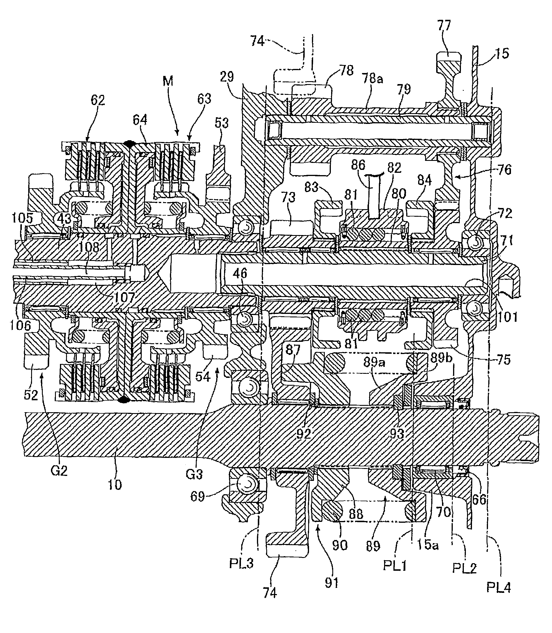
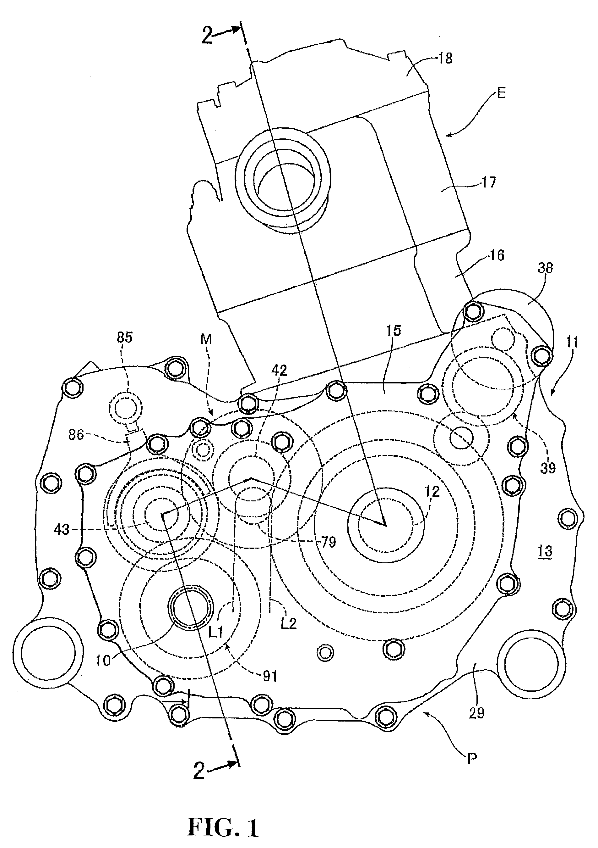
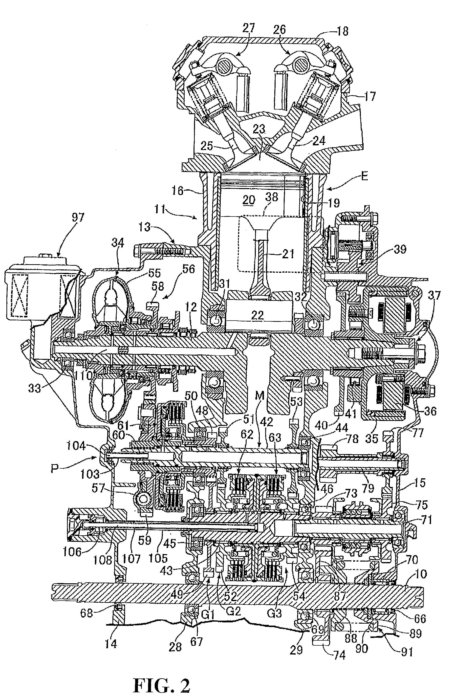
[0028]An embodiment of the present invention is described with reference to FIGS. 1 to 4. As shown in FIGS. 1 and 2, this power unit P includes an engine E, and a speed change gear M which can change the speed of rotational power inputted thereto from the engine E stepwise. The rotational power transmitted from the speed change gear M is outputted from a final shaft 10.

[0029]An engine body 11 of the engine E includes a crankcase 13 for supporting a crankshaft 12 for rotation thereon, a first crankcase cover 14 fastened to the crankcase 13 and covering one side of the crankcase 13 in a direction along an axial line of the crankshaft 12, a second crankca...


PUM


Abstract

A power unit for a vehicle includes a buffering device provided on a final shaft parallel to a countershaft of a speed change gear which is configured to change a speed resulting from rotational power inputted from an engine stepwise. The buffering device includes a damper gear wheel supported for relative rotation on the final shaft, a lifter coupled against relative rotation but for relative movement in an axial direction on the final shaft and engaged by a cam provided on one face of the damper gear wheel, a spring retainer supported at a position on the final shaft spaced apart from the lifter, and a coil spring provided between the lifter and the spring retainer in such a manner as to exert spring force for biasing the lifter toward the damper gear wheel. The power unit carries out changeover between a state where the rotational power in a forward direction from the countershaft is transmitted to the damper gear wheel and another state wherein the rotational power in a reverse direction from the countershaft is transmitted to the damper gear wheel through a reverse gear train including idle gear wheels supported for rotation on the countershaft and an idle shaft extending in parallel to the final shaft. The buffering device is disposed on the final shaft and positioned between a pair of imaginary planes, the pair of imaginary planes extending perpendicularly to an axial line of the idle shaft and passing opposite ends of the idle shaft.

Description

CROSS-REFERENCE TO RELATED APPLICATIONS[0001]This nonprovisional application claims priority under 35 U.S.C. §119(a) on Patent Application No. 2009-225476, filed in Japan on Sep. 29, 2009, the entirety of which is incorporated herein by reference.BACKGROUND OF THE INVENTION[0002]1. Field of the Invention[0003]This invention relates to a power unit, and more particularly to a power unit for a vehicle.[0004]2. Background of the Invention:[0005]As disclosed in Japanese Utility Model Laid-Open No. Sho 59-191453, in a power unit for a vehicle, a buffering device is provided between a countershaft of a speed change gear and a final shaft parallel to the countershaft. The buffering device includes a damper gear to which rotational power from the countershaft is transmitted, a lifter engaged by a cam provided on one face of the damper gear, a spring retainer supported on the final shaft, and a coil spring provided between the lifter and the spring retainer for exerting spring force for bias...

Claims


Application Information

Patent Timeline
Patent Type & Authority Applications(United States)
IPC IPC(8): F16H55/14F16C19/46F16F15/123F16H3/091F16H57/04
CPCY10T74/19633F16H55/14Y10T74/19233
Inventor SOTANI, HIROSHI
Owner HONDA MOTOR CO LTD
Why Eureka
Try Eureka