Vaporizer with foil heat exchanger

a technology of heat exchanger and vaporizer, which is applied in the field of vaporizers with foil heat exchangers, can solve the problems of device sacrificing one of the significant benefits of employing a vaporizer, user exposed to combustion byproducts, and limited to a single use, so as to achieve the effect of minimizing expansion and flex

Active Publication Date: 2011-03-31
VAPMAN GMBH SRL
View PDF9 Cites 100 Cited by
  • Summary
  • Abstract
  • Description
  • Claims
  • Application Information

AI Technical Summary

Benefits of technology

[0011]In another aspect, the heat exchanger member preferably has a concave depression on the first face configured to deflect heat from the combustion source away from the member periphery and heat exchanger frame. Also ...

Problems solved by technology

However, the inhalation air and the combustion air are not kept separate, causing the user to be exposed to the combustion byproducts.
As such, this device sacrifices one of the significant benefits of employing a vaporizer.
With no practical means for refueling such a device, it is limited to a single use.
In turn, this creates an uneven temperature profile and offers little control over maintaining the correct vaporization...

Method used


Image

  • Vaporizer with foil heat exchanger
  • Vaporizer with foil heat exchanger
  • Vaporizer with foil heat exchanger

Examples


Embodiment Construction

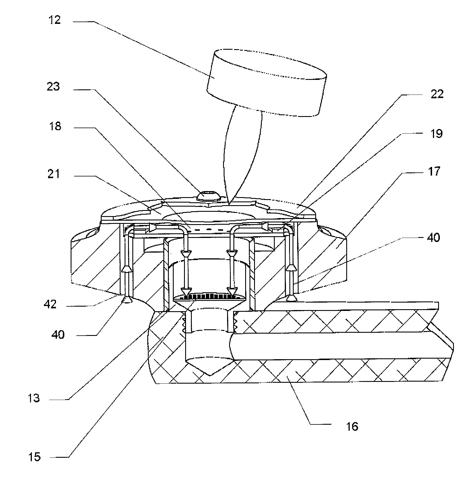
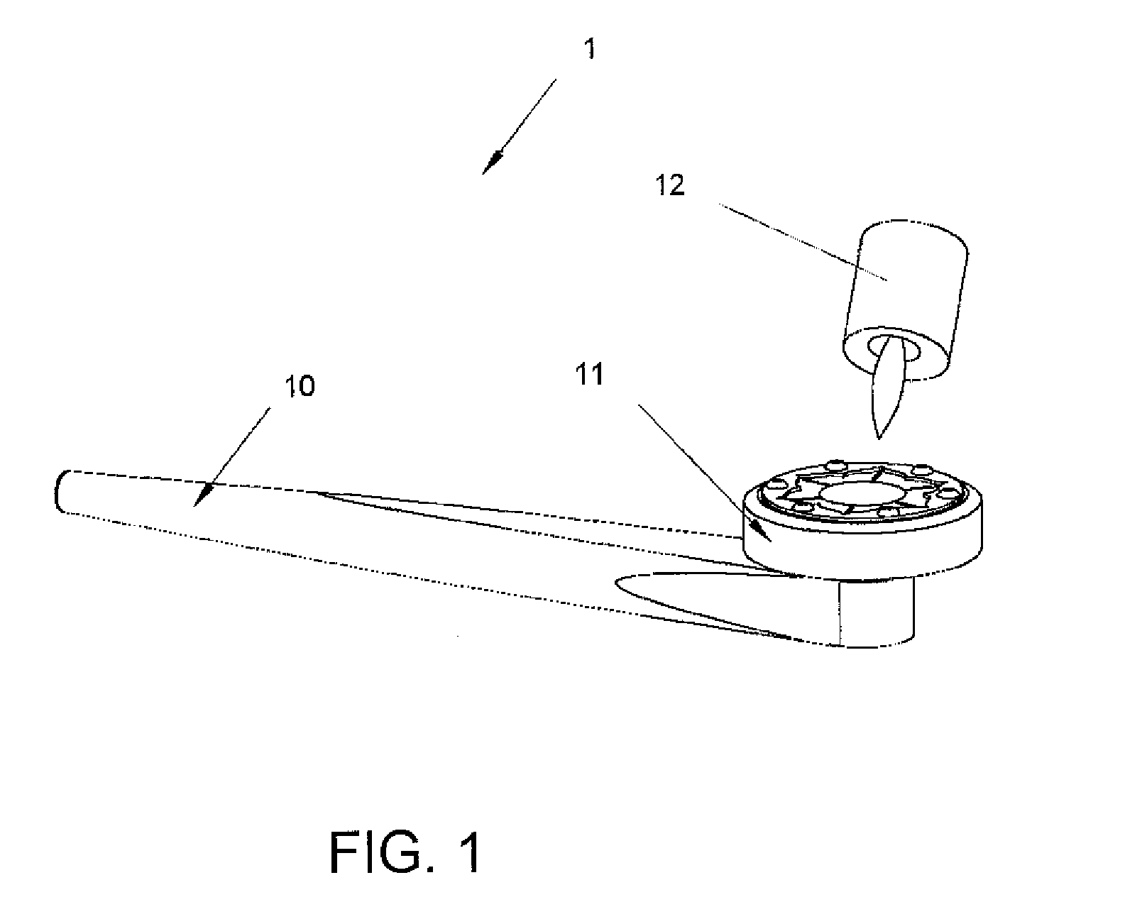
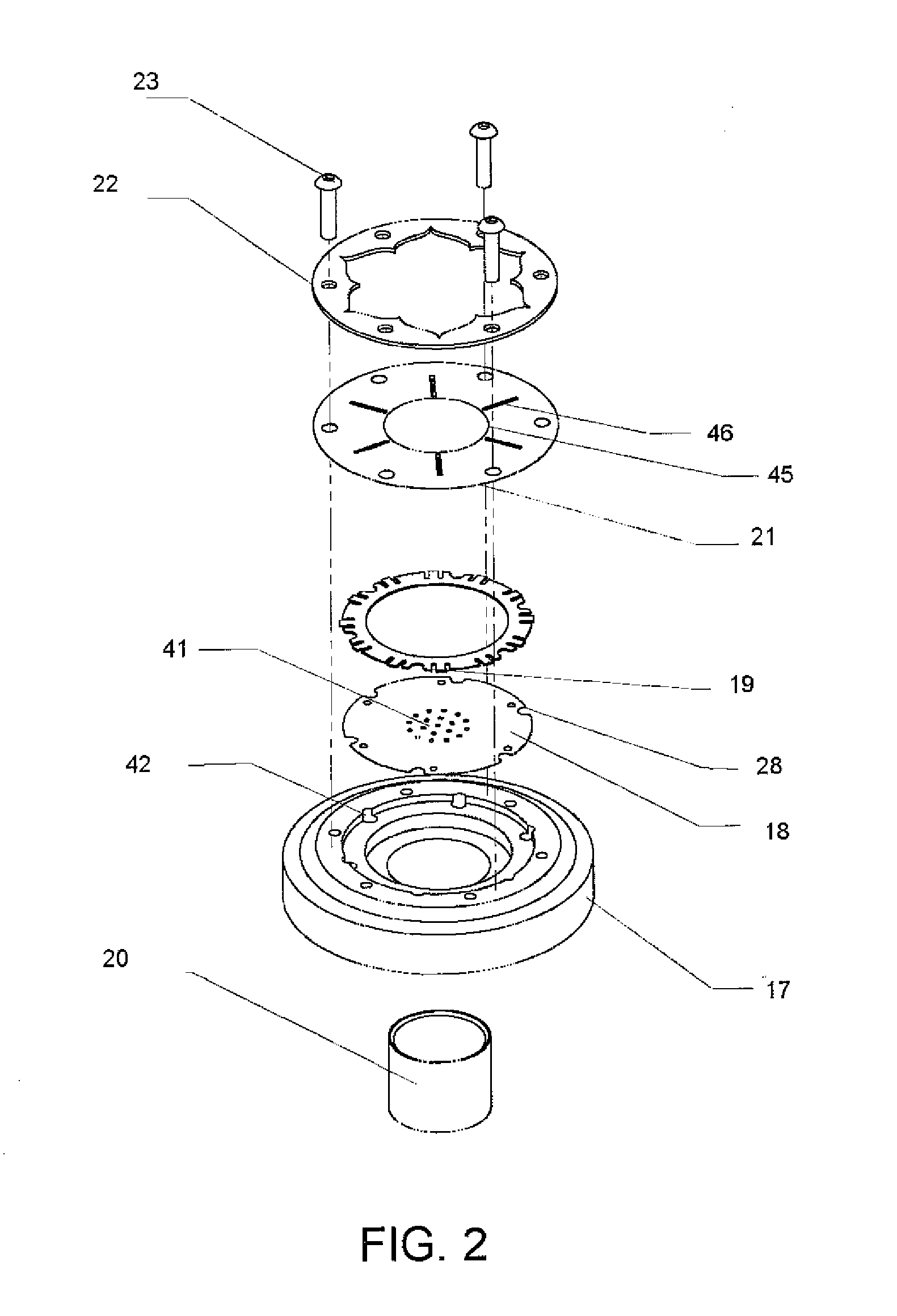
[0023]This disclosure is directed to the vaporization of a botanical substance for inhalation using a combustion generated heat source. A substantially planar non-porous heat exchanger transfers heat to the inhalation air and keeps combustion byproducts separated from the inhalation air. In use, air is drawn past the heat exchanger and then through a reservoir holding the botanical substance, vaporizing any volatiles in the substance. The heat exchanger assembly can be magnetically attached to the pipe assembly.

[0024]At the outset, it is to be understood that this disclosure is not limited to particularly exemplified materials, methods or structures as such may, of course, vary. Thus, although a number of materials and methods similar or equivalent to those described herein can be used in the practice of embodiments of this disclosure, the preferred materials and methods are described herein.

[0025]It is also to be understood that the terminology used herein is for the purpose of des...


PUM


Abstract

This invention vaporizes a botanical substance for inhalation using a combustion generated heat source. A substantially planar non-porous heat exchanger transfers heat to the inhalation air and keeps combustion byproducts separated from the inhalation air. In use, air is drawn past the heat exchanger and then through a reservoir holding the botanical substance, vaporizing any volatiles in the substance. The heat exchanger assembly can be magnetically attached to the pipe assembly.

Description

RELATED APPLICATIONS[0001]This application is related to and claims priority horn provisional application Ser. No. 61 / 277,822 filed on Sep. 29, 2009.FIELD OF THE PRESENT INVENTION[0002]The present invention generally relates to devices that vaporize volatile components of a botanical substance for human inhalation rather than combusting them. More specifically, the invention is directed to a vaporizer employing a combustion-generated heat source that offers rapid heating and cooling times while maintaining separation between inhalation air and combustion air.BACKGROUND OF THE INVENTION[0003]Vaporization provides a desirable alternative to combustion for the delivery and consumption of botanical substances. Because vaporization can aerosolize components of botanical substances at a lower temperature than combustion, there is less heat-related degradation of the substances. Furthermore, vaporization avoids the generation of the noxious secondary compounds typically formed by direct co...

Claims


Application Information

Patent Timeline
IPC IPC(8): A24F1/32A24F47/00A24F42/10A24F42/60
CPCA24F47/006A24F1/32A24F42/10A24F42/60
Inventor LEVIN, STEVEN ELLIOTBLISS, DON BARKER
Owner VAPMAN GMBH SRL
Why Eureka
Try Eureka