
Flexible vibration absorbing tube

a vibration absorption tube and flexible technology, applied in the field of flexible tubes, can solve the problems of undetectable increase of the flow resistance of the exhaust gas, inability to effectively reduce the noise of the exhaust pipe or reduce the back pressure, and the flexible tube has to be larger in size, so as to achieve the effect of reducing production costs and being easy to produ

Active Publication Date: 2011-03-31
HONDA MOTOR CO LTD +1
View PDF13 Cites 26 Cited by
  • Summary
  • Abstract
  • Description
  • Claims
  • Application Information

AI Technical Summary

Benefits of technology

nd portions of the interlock tube, advantageous effects similar to those obtainable by the first aspect and feature of the present invention can be obtained. In addition, the flexible tube provided by the second aspect and feature of the present invention can be more easily produced than the flexible tube provid

Problems solved by technology

However, the expansion of the exhaust-gas passage by such “coupling step” fails to effectively reduce the exhaust noise or to reduce the back pressure (a pressure preventing the exhaust gas from being discharged).
Further, the very existence of the “coupling step” requires the outer diamet

Method used


Image

  • Flexible vibration absorbing tube
  • Flexible vibration absorbing tube
  • Flexible vibration absorbing tube

Examples


Embodiment Construction

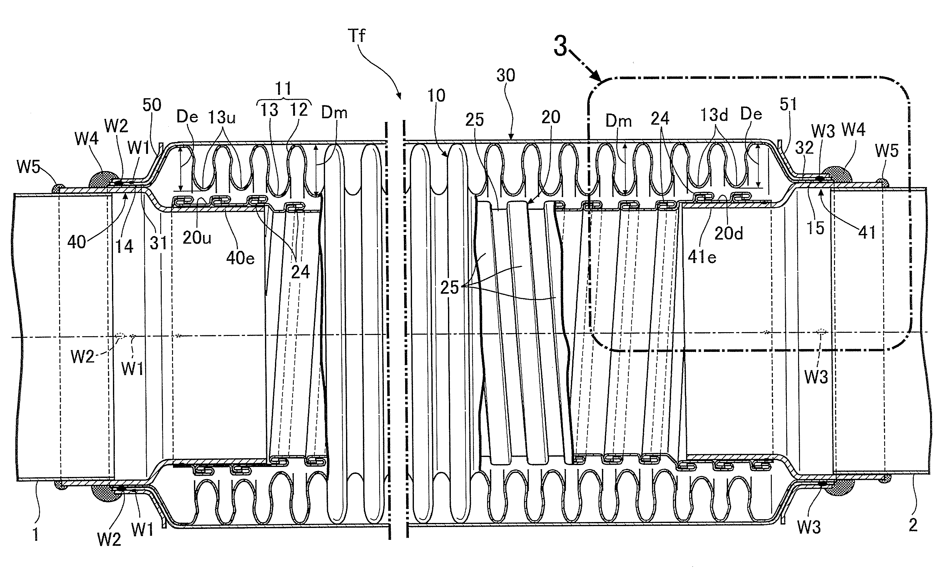
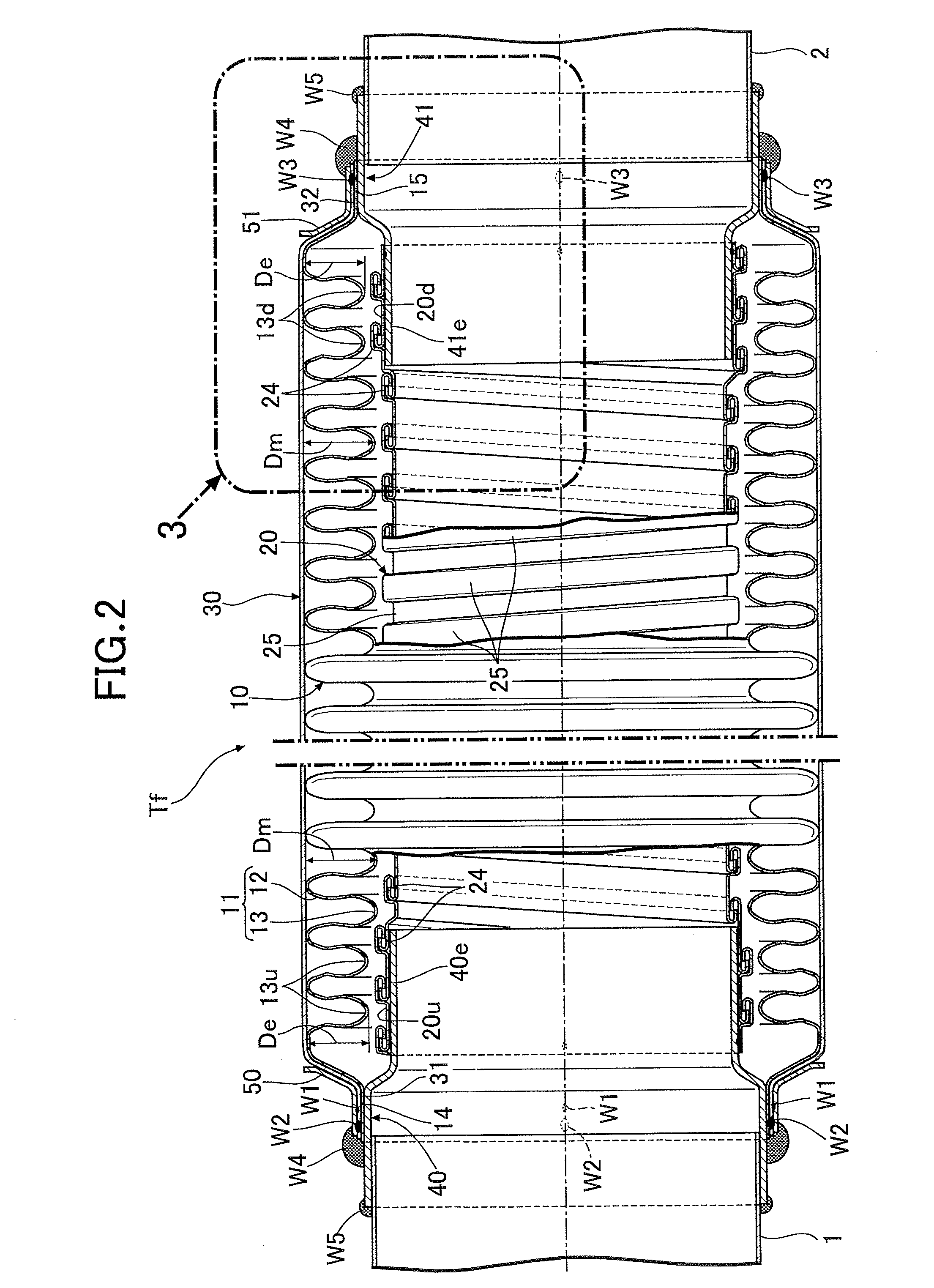
Hereinafter, descriptions will be provided for the exemplary embodiments of the present invention shown in the attached drawings.

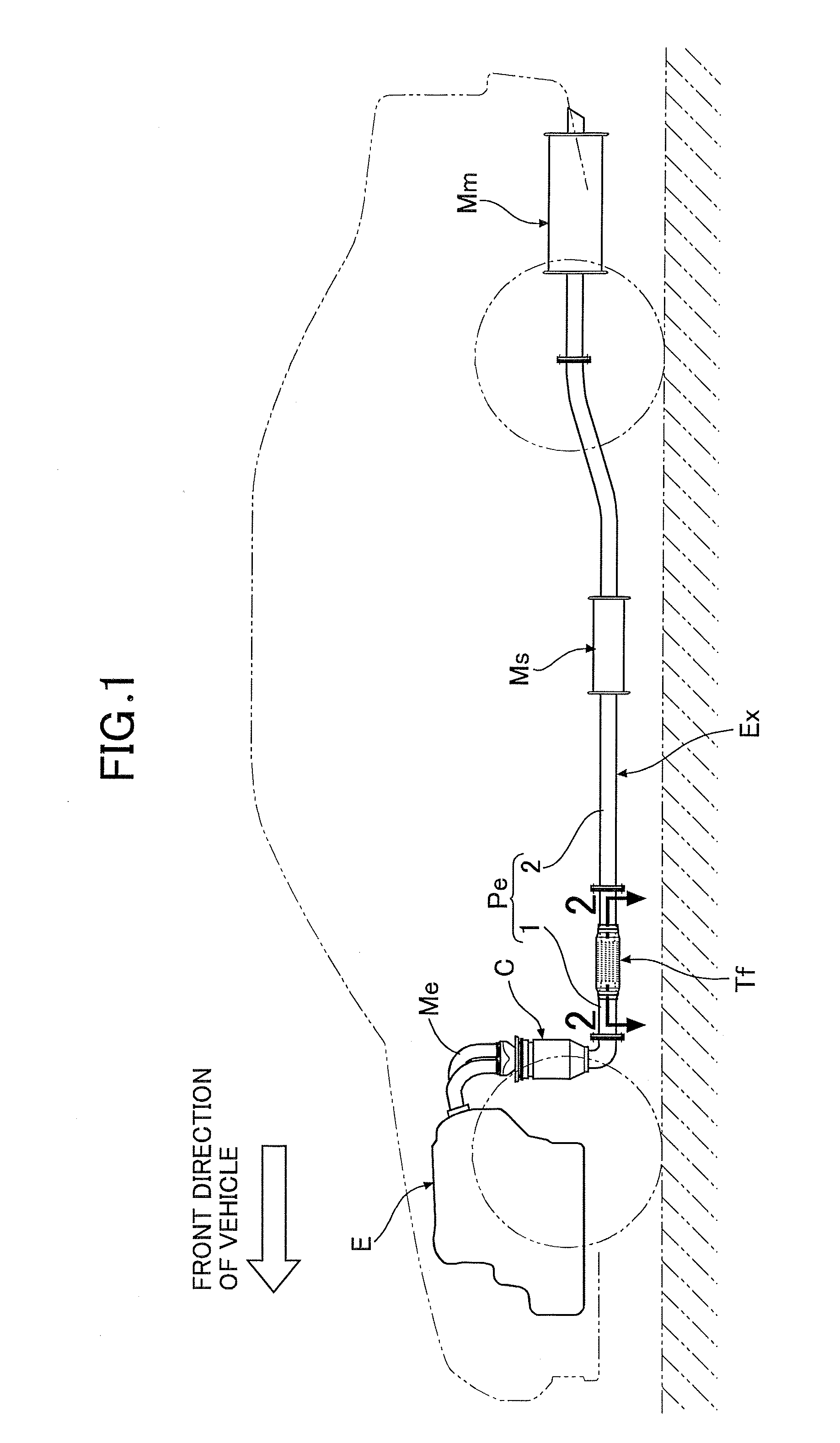
The exemplary embodiments concern a case where the flexible tube of the present invention is applied to the exhaust system of an engine for an automobile. In the following description, the terms indicating directions, such as, “front,”“rear,”“right,”“left,”“up,” and “down” are defined using the direction in which the automobile moves forward, as the reference.

In FIG. 1, in a front portion of an automobile, an engine E for driving the automobile is mounted in a transverse manner (with a crankshaft of the engine E extending in the right-and-left direction of the vehicle), and an exhaust system EX is connected to an exhaust port opened in the back-side surface of a top portion of the engine E. In the exhaust system EX, an exhaust pipe Pe is connected to the downstream side of an exhaust manifold Me connected integrally to the exhaust port. The exhaust pipe Pe...


PUM


Abstract

A flexible tube includes a bellows tube, an interlock tube placed inside the bellows tube, and upstream-side and downstream-side joint pipes coupled to opposite ends of the bellows tube. Diameters of fixing end portions located at opposite ends of the interlock tube are made larger than a diameter at a middle portion of the interlock tube, extension portions of the upstream-side and downstream-side joint pipes are fitted and fixed to inner peripheral surfaces of the fixing end portions of the interlock tube, and a depth of each of valley portions of a bellows portion of the bellows tube located over the fixing end portions is smaller than a depth of other valley portions of the bellows portion. Accordingly, it is possible to achieve the downsizing of the flexible tube that is connected to an exhaust system being continuous with an engine to dampen vibrations in the axial direction of the exhaust system.

Description

CROSS-REFERENCE TO RELATED APPLICATIONSThe present application claims priority under 35 USC §119 based on Japanese patent application No. 2009-228073, filed 30 Sep. 2009. The subject matter of this priority document is incorporated herein by reference.BACKGROUND OF THE INVENTION1. Field of the InventionThe present invention relates to a flexible tube, and particularly to a flexible tube serving as a vibration-absorbing pipe connected to the exhaust system of an engine mainly for vehicles or the like to absorb the vibrations from the engine.2. Description of the Related ArtThe exhaust system for a vehicle is conventionally formed by connecting a catalytic converter, a sub muffler, a main muffler, and the like to an exhaust pipe extending from an exhaust manifold of an engine. To prevent the propagation of vibrations from the engine to the mufflers and the like situated at the rear stage of the exhaust system, it is known, for example, to provide a flexible tube serving as a vibration...

Claims


Application Information

Patent Timeline
IPC IPC(8): F16L11/00
CPCF01N13/1816F16L11/16F16L51/027F16L51/025F16L27/111
Inventor EGUCHI, YOSHIHIKOHIGUCHI, MASAHIKOHARADA, KOUJIGUSHIKEN, YOSHIYUKIFUKAZAWA, JUN
Owner HONDA MOTOR CO LTD
Features
  • Generate Ideas
  • Intellectual Property
  • Life Sciences
  • Materials
  • Tech Scout
  • Unparalleled Data Quality
  • Higher Quality Content
  • 60% Fewer Hallucinations
Learn More