Heat dissipation system

a heat dissipation system and heat dissipation technology, applied in the direction of electrical apparatus casings/cabinets/drawers, instruments, semiconductor/solid-state device details, etc., can solve the problems of deteriorating the operation stability, damage to associated electronic components, and heat dissipation

Inactive Publication Date: 2011-03-31
HONG FU JIN PRECISION IND (SHENZHEN) CO LTD +1
View PDF17 Cites 4 Cited by
  • Summary
  • Abstract
  • Description
  • Claims
  • Application Information

AI Technical Summary

Problems solved by technology

Electronic components, such as central processing units (CPUs), generate heat during normal operation, which can deteriorate their operational stability, and damage associated electronic components.
The heated airflow is tends to be reflected by other components and causes interference in the computer case, which has an influence on other components' heat dissipating and is not efficient.

Method used


Image

  • Heat dissipation system
  • Heat dissipation system
  • Heat dissipation system

Examples


Embodiment Construction

[0009]The disclosure is illustrated by way of example and not by way of limitation in the figures of the accompanying drawings in which like references indicate similar elements. It should be noted that references to “an” or “one” embodiment in this disclosure are not necessarily to the same embodiment, and such references mean at least one.

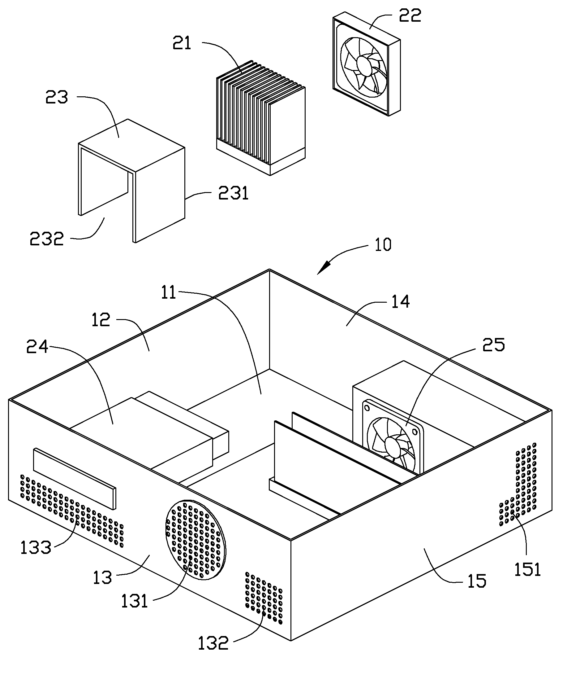
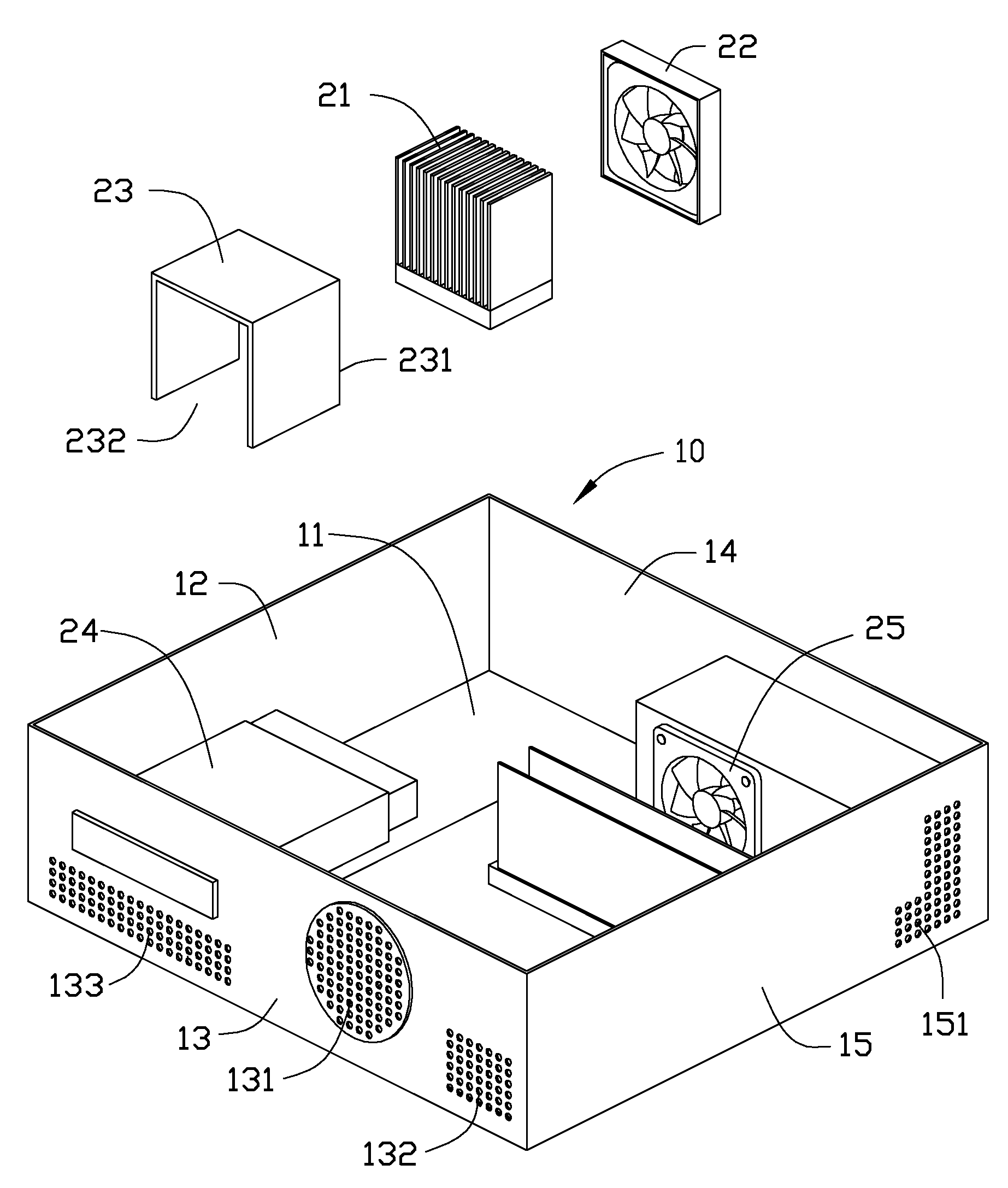
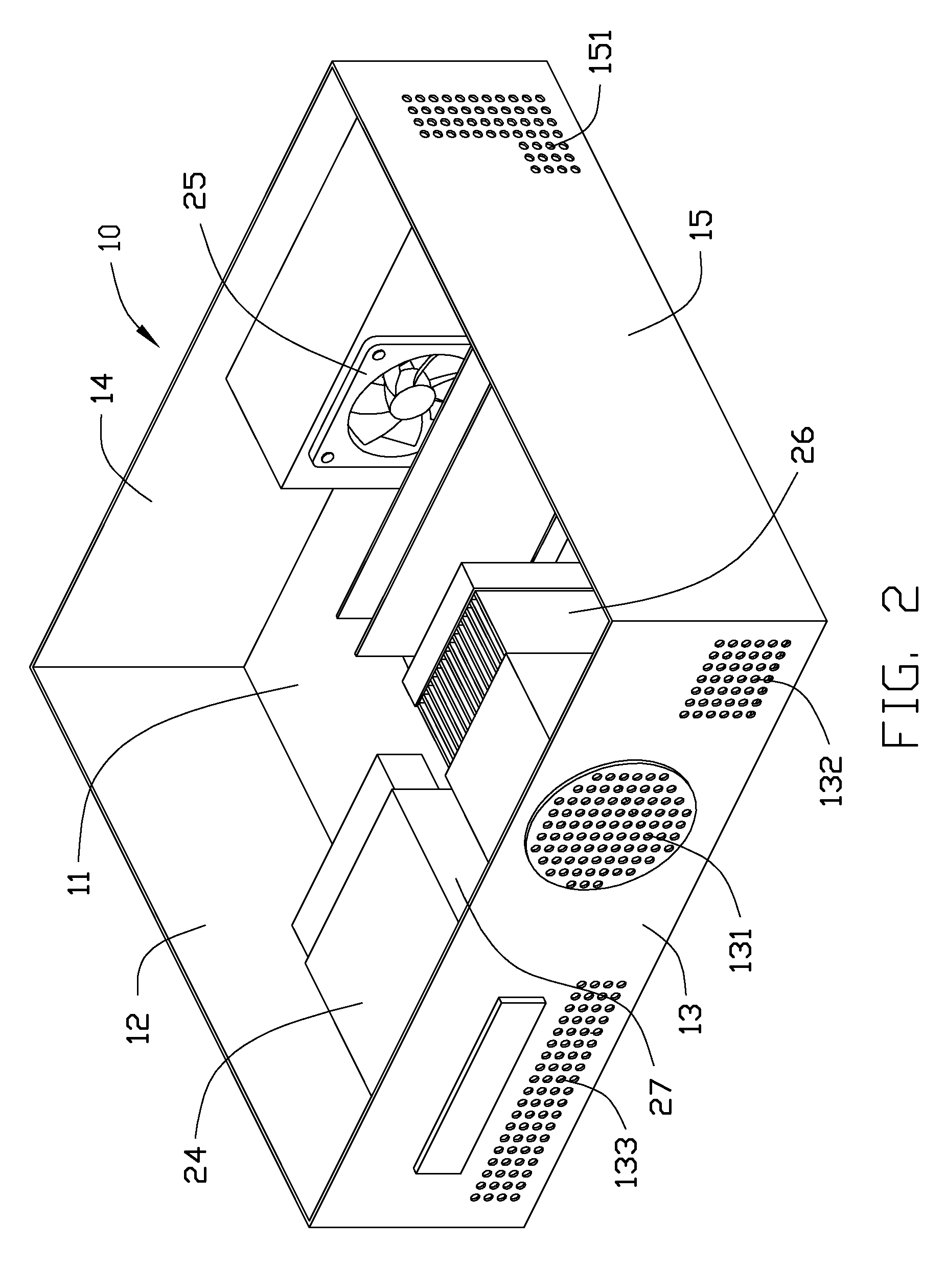
[0010]Referring to FIGS. 1 and 2, a heat dissipation system for a computer case 10 includes a base plate 11, a front plate 12, a first side plate 13, a second side plate 14 and a back plate 15. The base plate 11 has a motherboard (not labeled) attached. The motherboard is installed with a first heat source (not shown). A heat sink 21 is positioned on the first heat source adjacent to the back plate 15. A first fan 22 is positioned on the motherboard adjacent to a first side of the heat sink 21. An air duct 23 is positioned on the motherboard adjacent to a second side of the heat sink 21. The heat sink 21 is capable of heating air blown from first...


PUM


Abstract

A heat dissipation system includes a computer case has a base plate and a back plate perpendicularly to the base plate, a heat sink, a first fan and an air duct. The heat sink is positioned in the computer case in contact with a first heat source. The first heat source and the back plate define a first air channel therebetween. The first fan is positioned in the computer case adjacent to a first side of the heat sink. The first fan is configured to generate airflow through the heat sink in such a manner that airflow flows from the computer case outside is sucked into the computer case via the first air inlet and the first air channel. The air duct is positioned in the computer case adjacent to a second side of the heat sink. The heat sink heats the airflow from the first fan. The warm airflow heated by the heat sink is then blown out of the computer case by the first fan via the air duct.

Description

BACKGROUND[0001]1. Technical Field[0002]The present disclosure relates to a heat dissipation system.[0003]2. Description of Related Art[0004]Electronic components, such as central processing units (CPUs), generate heat during normal operation, which can deteriorate their operational stability, and damage associated electronic components. Thus, the heat must be removed quickly to ensure normal operation of the CPU. A typical heat dissipation system includes a CPU fan and a system fan in a computer case. A heat sink is mounted on the CPU to remove heat, and the CPU fan is fixed on the heat sink to generate airflow through the heat sink. The airflow passes through the heat sink and is temperature increased by the heat generated by the CPU. The heated airflow is then taken out of the computer case by the system fan. The heated airflow is tends to be reflected by other components and causes interference in the computer case, which has an influence on other components' heat dissipating an...

Claims


Application Information

Patent Timeline
Patent Type & Authority Applications(United States)
IPC IPC(8): F24H9/02F28D15/00
CPCG06F1/20G06F1/181
Inventor HUANG, GUO-HE
Owner HONG FU JIN PRECISION IND (SHENZHEN) CO LTD
Why Eureka
Try Eureka