Electric power tool

Inactive Publication Date: 2011-03-31
PANASONIC ELECTRIC WORKS POWER TOOLS
View PDF60 Cites 68 Cited by
  • Summary
  • Abstract
  • Description
  • Claims
  • Application Information

AI Technical Summary

Benefits of technology

[0009]The present electric power tool can prevent the wireless communication device from being broken due to the collision with the surrounding structu

Problems solved by technology

With the electric power tools cited above, there is a likelihood that the wireless communication device arranged inside the housing may collide with the surrounding structures due to the vibration generated during works and may eventually be broken

Method used


Image

  • Electric power tool
  • Electric power tool
  • Electric power tool

Examples


Embodiment Construction

[0016]One embodiment of an electric power tool in accordance with the present invention will now be described with reference to the accompanying drawings which form a part hereof.

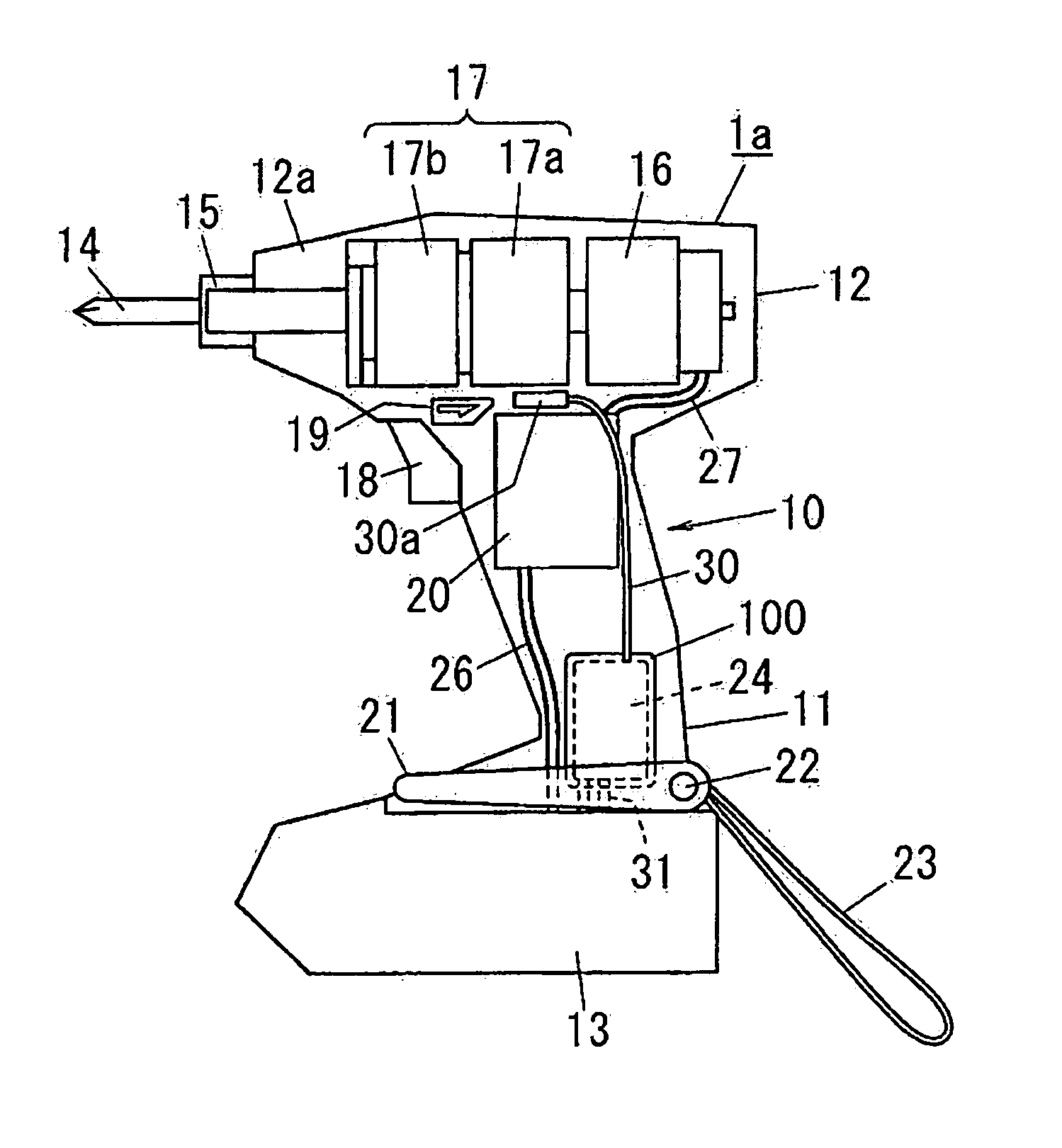
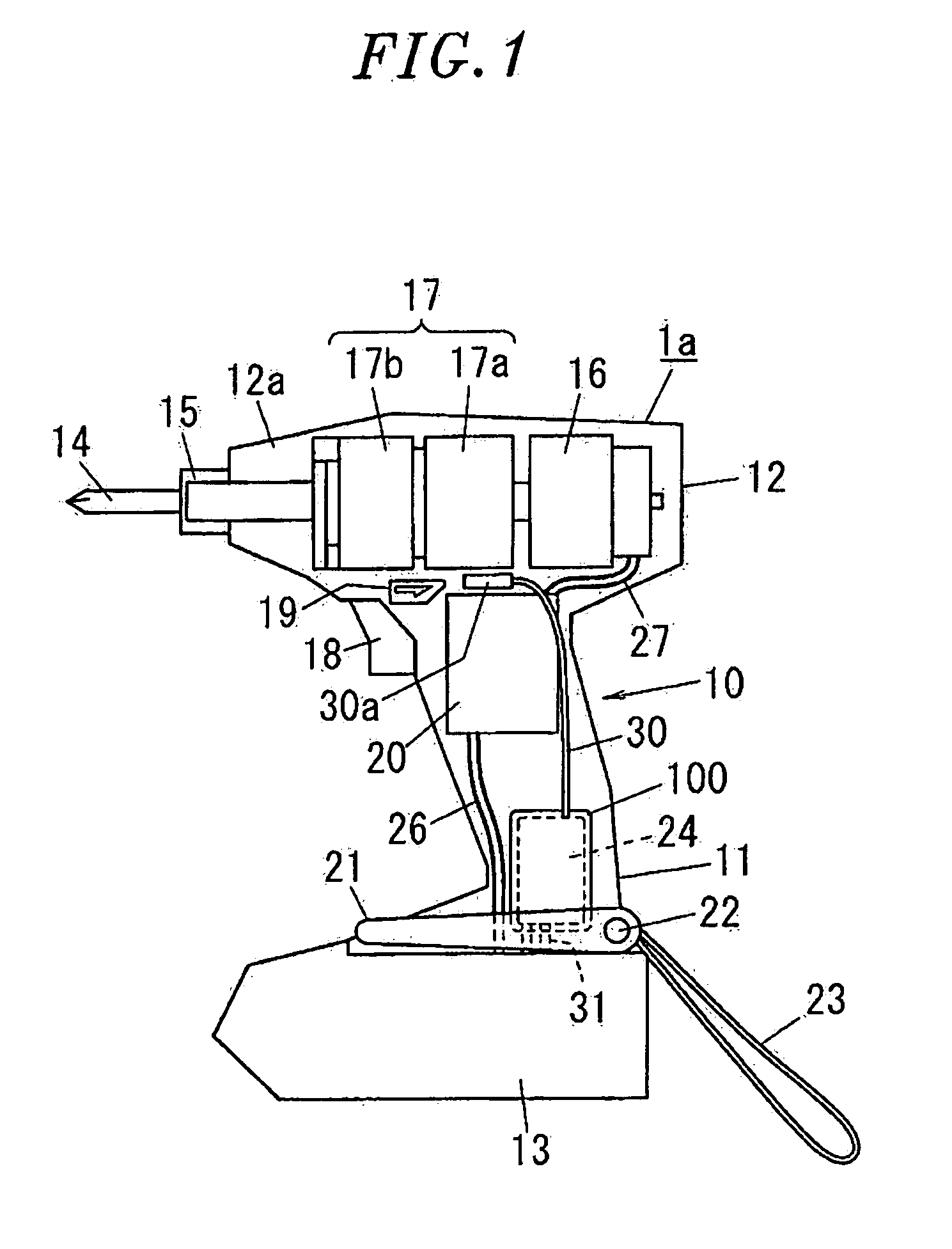
[0017]Referring to FIG. 1, an electric power tool 1a includes a hollow tubular grip 11 formed into a hand-held size and a hollow tubular body 12 provided at one axial end (upper end) of the grip 11. The body 12 has an axis intersecting the axis of the grip 11 so that the body 12 and grip 11 can make a substantially “T”-shape when seen in a side view. The electric power tool 1a further includes a battery holder 13 provided at the other axial end (lower end) of the grip 11. The grip 11, the body 12 and the battery holder 13 make up a housing 10 of the electric power tool 1a. A rechargeable battery (not shown) is accommodated within the battery holder 13 removably attached to the lower end portion of the grip 11. Electric power for operation of the electric power tool 1a is supplied from the rechargeable batte...


PUM


Abstract

An electric power tool includes a housing, a motor arranged within the housing, a power transmission unit arranged within the housing for transferring rotation of the motor to a work tool, a motor control unit arranged within the housing for controlling the rotation of the motor, and a trigger switch retractably provided to the housing for instructing the motor control unit to control the rotation of the motor. The electric power tool further includes a wireless communication device arranged within the housing for wirelessly communicating the work information on the content of works. The wireless communication device includes an antenna unit. The wireless communication device is covered with a shock-absorbing material. The antenna unit is arranged to lie higher than the trigger switch when the electric power tool is stored in a specified storage state.

Description

FIELD OF THE INVENTION[0001]The present invention relates to an electric power tool having a wireless communication function by which the work information on the content of works can be wirelessly communicated between the electric power tool and the outside.BACKGROUND OF THE INVENTION[0002]Conventionally, there is proposed an electric power tool that includes, as shown in FIG. 4, a housing 10 and a wireless communication device 24 arranged inside the housing 10, the wireless communication device 24 having an antenna unit 30a for transmitting information, e.g., the fastening torque, to a controller for managing a screw tightening work, only the antenna unit 30a being arranged outside the housing (see, e.g., Japanese Patent Application Publication No. H06-312381).[0003]Also proposed is an electric power tool that includes, as shown in FIG. 5, a housing 10 and a wireless communication device 24 arranged inside the housing 10, the wireless communication device 24 having an antenna unit ...

Claims


Application Information

Patent Timeline
IPC IPC(8): B25F5/00
CPCB25F5/006B25F5/00
Inventor SAWANO, FUMIAKISHIMIZU, HIDENORIMIYAZAKI, HIROSHI
Owner PANASONIC ELECTRIC WORKS POWER TOOLS
Why Eureka
Try Eureka