Laminar flow water jet with wave segmentation, additive, and controller

a technology of additives and water jets, applied in the field of water features, can solve problems such as interruption of columnar length, rod structure, and interference of water jets, and achieve the effects of reducing the number of water jets

Active Publication Date: 2011-03-31
PENTAIR WATER POOL & SPA INC
View PDF46 Cites 13 Cited by
  • Summary
  • Abstract
  • Description
  • Claims
  • Application Information

AI Technical Summary

Benefits of technology

[0013]Yet another object of the invention is to provide enhanced illumination to the laminar flow tube through the dripping of an additive, the absorption of the additive admitting air bubbles or a turbulence to the laminar flow segment internally but maintaining the laminar flow segments surface structure.
[0035]The method of the invention includes a method of providing multiple colors within a laminar flow of water, including the steps of providing a laminar flow of water, lighting the laminar flow of water, inputting an energetic pulse wave or an additive wave or flow to disrupt the laminarity of the water flow at a specific part and provide discreet segmentation of the laminar flow of water without significantly disrupting the laminar flow jet, and changing the light color between different discrete segments in the laminar flow jet. The method of providing multiple colors within a laminar flow further provides the method step of jetting the laminar flow of water into a laminar flow tube. The method of providing multiple colors can also include the method step of columnarizing the laminar flow tube, wherein discrete columns are created in laminar flow tube with the discrete segmentation therein, and the columns being points where the laminar flow tube is broken apart into a variety of segments.

Problems solved by technology

This results in the smooth rod structure of the streams that are issued from the jets.
This results in an interruption of the columnar length prior to its emergence from the device.
However, these devices do not permit interruption of the laminarity without diversion of the flow jet or disruption of the column of the jet and, further, the devices do not provide a controllable energetic impulse or pulse to interrupt the jet without breaking the tube up in either the horizontal or vertical direction.
This design however fails to provide a pulse wave or any similar disruption of the flow in a laminar flow water jet.
Although there are devices available that add vibratory or oscillatory pulses into a water stream, for instance in U.S. Pat. No. 3,924,808 that shows a shower head vibrator is attached to the resilient coupling provided between the water outlet pipe and the shower head that produces an oscillatory pattern in the flow, these devices do not provide the controlled interruption necessary to maintain laminarity in a laminar flow water column.
To date, no method has been able to selectively interrupt the laminarity within or about the laminar jet tube of a laminar water jet without significant visible disruption or diversion of the laminar jet.
Moreover, no method to date has allowed for a level of variation in the interruption of the laminarity in the laminar jet tube that would allow for both discrete jet tube lengths, i.e. columnarization, as well as multiple segments within a tube or columnarized flow, i.e. discrete segmentation.
Further none of the existing devices allow for reflection enhancing perturbations from an additive drip in the jetted laminar flow tube.
Furthermore, no system can produce columnarization or segmentation and allow for discrete multiple color effects in the tubes or in columns.

Method used


Image

  • Laminar flow water jet with wave segmentation, additive, and controller
  • Laminar flow water jet with wave segmentation, additive, and controller
  • Laminar flow water jet with wave segmentation, additive, and controller

Examples


Embodiment Construction

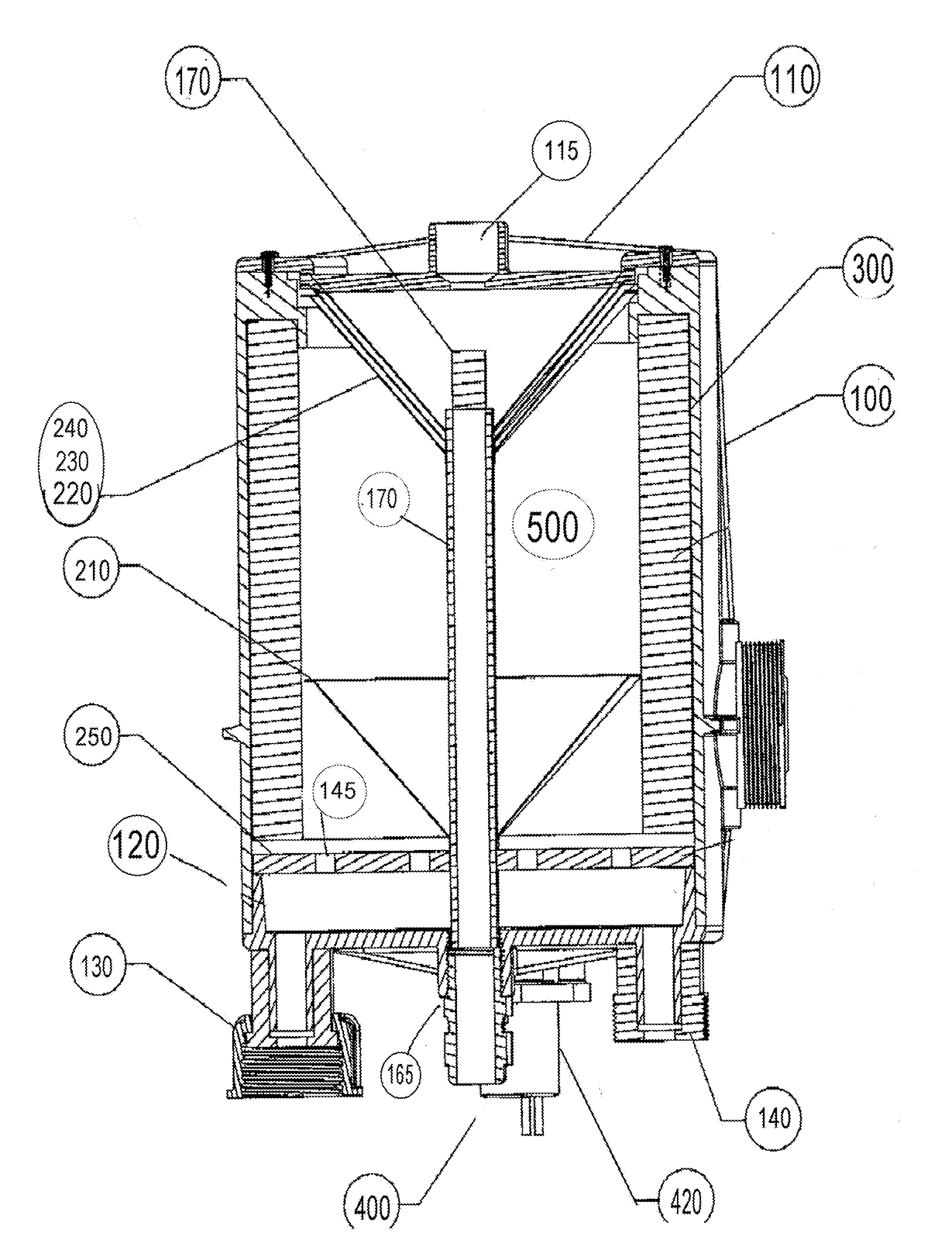
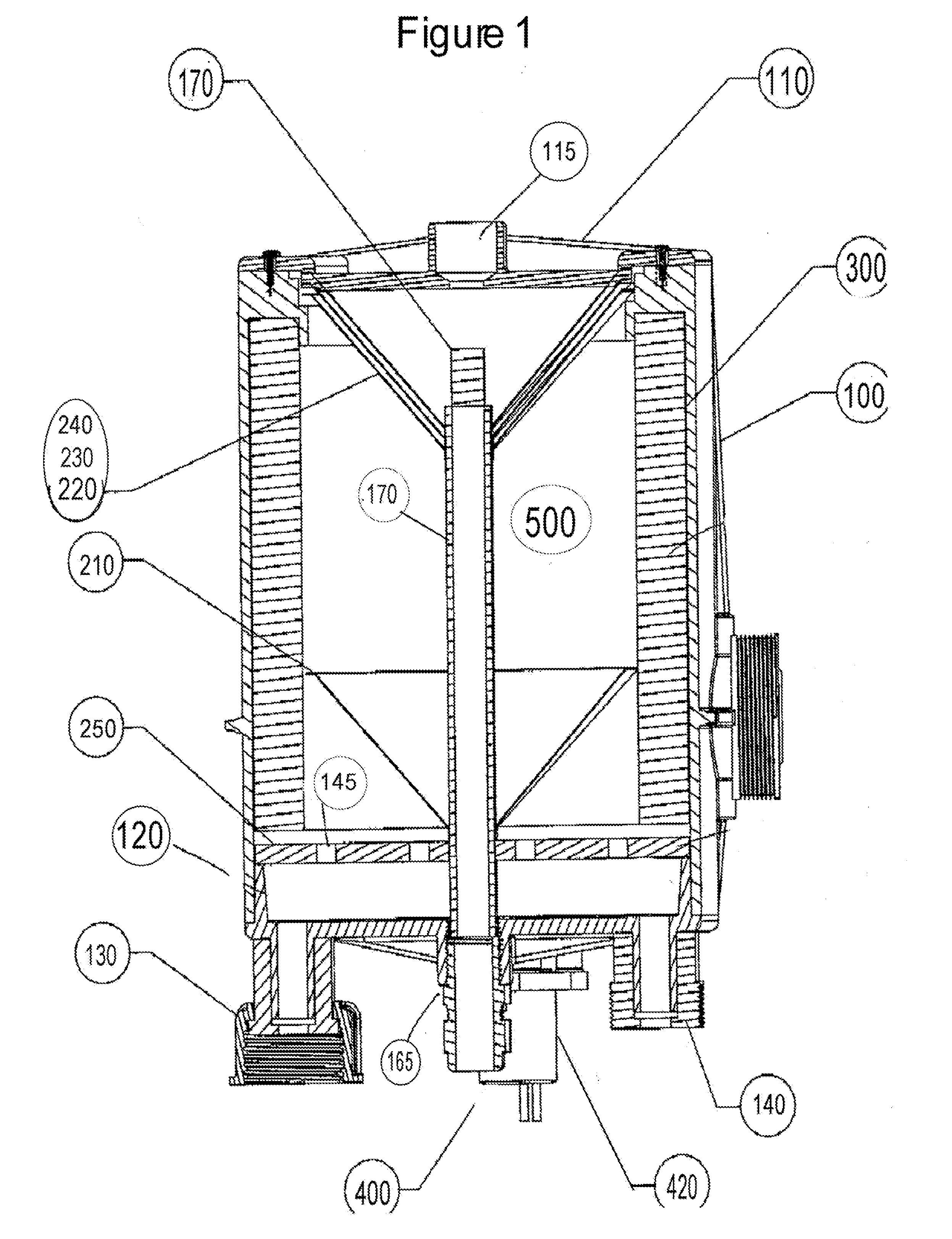
[0051]FIG. 1 shows a cross sectional view of the exemplary embodiment of the instant invention. The exemplary embodiment of FIG. 1A comprises a housing 100, a housing top 110 with an at least one jet element 115 extending there through, and a housing base 120. Flowing into the housing base 120 is an at least one water input, in this instance a first water input 130 and a second water input 140. Within the housing 100 a laminar water flow channel 500 resides. Additionally, a lighting orifice 165 is provided and passes through the base plate to couple to a lighting tube 170. The lighting tube 170 extends into the laminar water flow channel 500 and through the housing 100 toward the at least one jet element 115. The lighting tube 170 is provided to apply lighting effects to the exiting water. The tube may utilize any appropriate lighting system, including but not limited to, conventional incandescent, halogen, fiber optic, LED, nano scale lighting devices or similar lighting systems. F...


PUM


Abstract

A laminar flow water jet system has a housing with a water channel, the housing creating a laminar flow in the water channel from the water flowing through the housing. A lighting element is provided with a controller. The laminar flow passes through at least one jetting element having a cup portion and a nozzle portion and jetting a laminar flow tube from the laminar flow passing through the water channel in the housing at the base portion. The laminar flow tube is ejected from the nozzle as a laminar flow jet having a smoothed tubular surface jacket and being lit by the lighting element. An additive source drips additive into the cup portion at a rate controlled by the controller, the additive being absorbed by capillary action by the laminar flow tube as it is passed through the nozzle to become the laminar flow jet. The absorption process drawing in air from the surrounding atmosphere and creating perturbations or bubbles within the laminar flow tube. In a further mode either an energetic pulse or an additive wave formed by increasing the volume of additive in the cup portion of the jetting element creates a wave perturbation or interruption throughout the laminar flow tube creating a variation in the laminar flow tube and the smoothed tubular surface jacket of the resulting laminar flow jet.

Description

CROSS REFERENCE TO RELATED APPLICATIONS[0001]This application is a continuation in part application of U.S. patent application Ser. No. 11 / 280,392 filed Nov. 17, 2005, which is incorporated herein by reference.FIELD OF THE INVENTION[0002]The invention relates to a water feature, specifically a controller and apparatus that imparts an energetic pulse wave or additive flood wave into the smooth jacket of water held by surface tension making up the outside of a laminar flow tube issuing from, for instance, a laminar flow water jet.BACKGROUND OF THE INVENTION[0003]It is often desired to utilize a fluid, such as water, as part of a display or attraction. Increasingly, the popularity of using water attractions as an integral part of domestic and commercial landscaping has moved architects and landscapers to push further and further into incorporating the decorative aspects of these water features into new buildings and building sites. These features are incorporated through swimming pools...

Claims


Application Information

Patent Timeline
Patent Type & Authority Applications(United States)
IPC IPC(8): B05B15/00
CPCB05B1/34B05B12/06B05B17/08F21Y2103/00F21S10/02F21W2121/02F21Y2101/02F21S8/00F21Y2115/10B05B1/3402
Inventor JOHNSON, BRUCE
Owner PENTAIR WATER POOL & SPA INC
Why Eureka
Try Eureka