Microvalve for control of compressed fluids

Inactive Publication Date: 2011-03-31
EASTMAN KODAK CO
View PDF25 Cites 39 Cited by
  • Summary
  • Abstract
  • Description
  • Claims
  • Application Information

AI Technical Summary

Benefits of technology

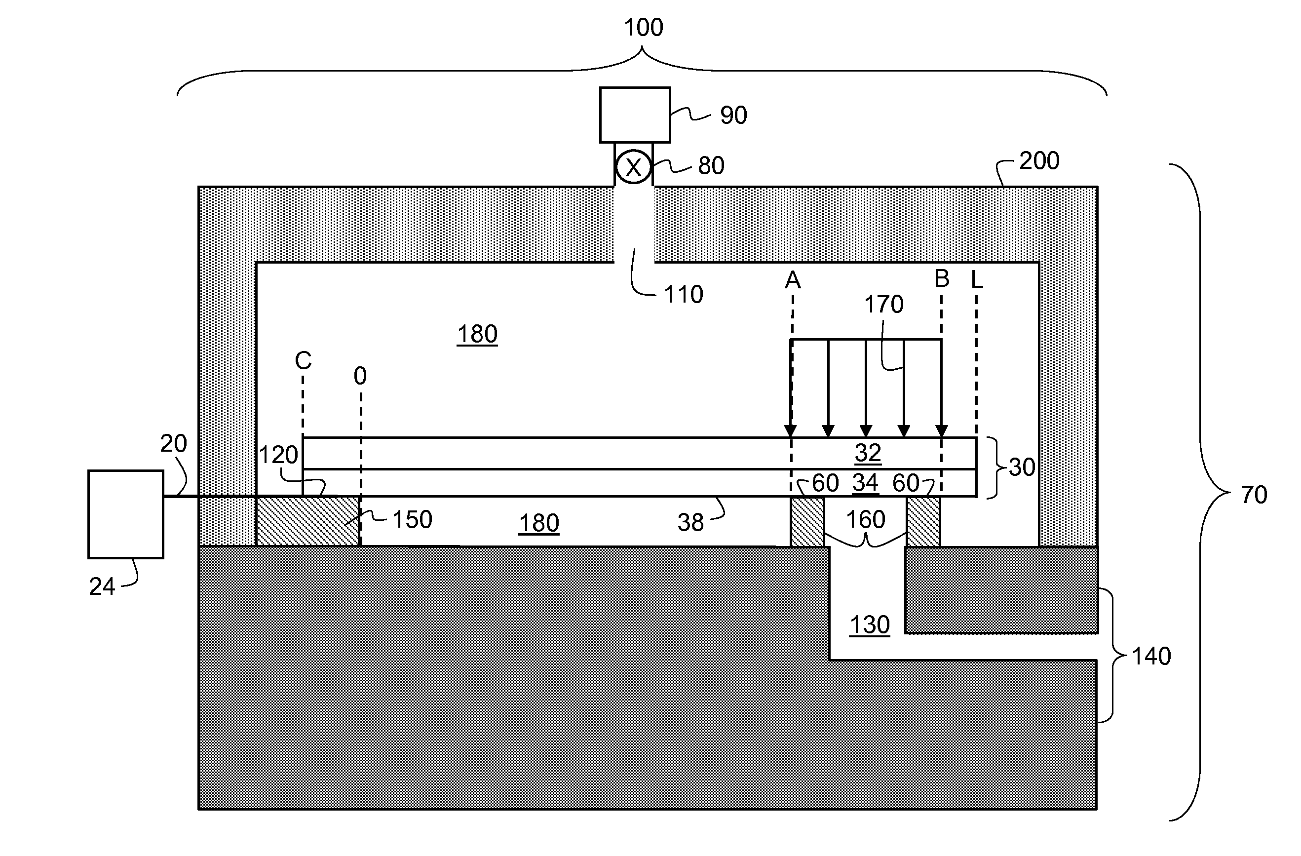
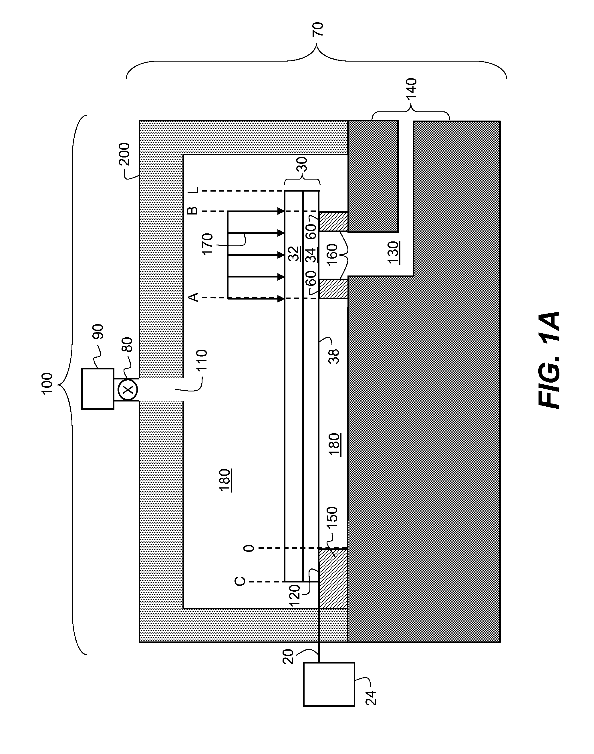
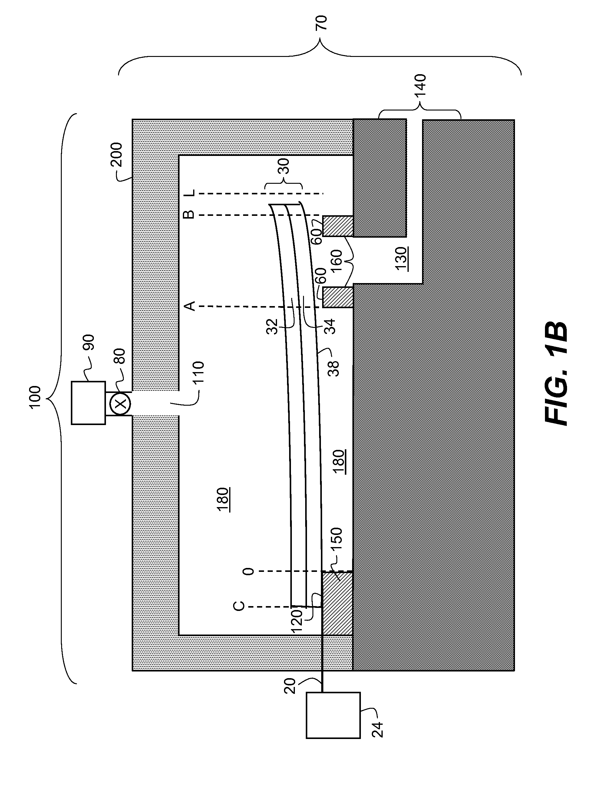
[0018]According to another aspect of the present invention, a method of controlling compressed fluid flow includes providing a source of compressed fluid; providing a compressed fluid microvalve including: a chamber including an inlet port, a region of high pressure, and an outlet port leading to a region of low pressure, the inlet port being in fluid communication with the source of compressed fluid; and a cantilever beam including a first portion, a second portion, and a third portion, the cantilever beam being anchored to a portion of the chamber and being suspended in the chamber such that the first portion and third portion of the cantilever beam are exposed to the region of high pressure on all sides, and the second portion of the cantilever beam overlaps the outlet port, the cantilever beam including a first position in contact with the outlet port to prevent fluid flow from the chamber through the outlet port and a second position removed from contact with the outlet port to: permit fluid flow from the chamber through the outlet port; providing a controller in electrical communication with the cantilever beam; and actuating the cantilever beam using the controller to move the cantilever beam from the first position in contact with the outlet port to the second position removed from contact with the outlet port.

Problems solved by technology

Hence, for sufficiently high pressures, such as those required for compressed fluids, a cantilever beam with, for example, thermal stimulation will have zero deflection across its length and will not open sufficiently.

Method used


Image

  • Microvalve for control of compressed fluids
  • Microvalve for control of compressed fluids
  • Microvalve for control of compressed fluids

Examples


example 1

[0068]The operation of a 200 μm long by 30 μm wide tri-layer thermo-mechanical micro-valve designed according to the teachings of this invention was mathematically modeled. The tri-layer valve had a 7 μm thick silicon nitride (Si3N4) layer sandwiched between two 7 μm thick aluminum layers. The part of the tri-layer valve in constant contact at the anchor was 20 μm long and it served as a heat sink. Also, the valve seat opening was 10 μm long by 20 μm wide and was located at 145 μm from the anchor. Initially, the valve was at 40 degree C. and 100 bar pressure in the high pressure chamber, forcing it in a closed position on the valve seat. Then a voltage pulse was applied to raise the temperature of the bottom aluminum layer 200 degree C. above the ambient (40 degree C.) in 1 μsec. The solid curve in FIG. 9 shows the calculated static deflection profile of the cantilever beam under these conditions. The pressure drop across the cantilever beam at the outlet port is calculated to be 46...

example 2

[0070]The operation of a 200 μm long by 30 μm wide bi-layer thermo-mechanical micro-valve designed according to the teachings of this invention was mathematically modeled. The bi-layer valve had 10 μm thick silicon nitride (Si3N4) top layer and a 10 μm thick aluminum bottom layer. The part of the bi-layer valve in constant contact at the anchor was 20 μm long and it served as a heat sink. Also, the valve seat was 10 μm long by 20 μm wide and was located at 110 μm from the anchor. Initially, the valve was at 40 degree C. and 150 bar pressure in the high pressure chamber, forcing it in a closed position on the valve seat. Then a voltage pulse was applied to raise the temperature of the bottom aluminum layer 200 degree C. above the ambient (40 degree C.) in 1 μsec. The solid curve in FIG. 11 shows the calculated static deflection profile of the cantilever beam under these conditions. The pressure drop across the cantilever beam at the outlet port is calculated to be 69 bar for the chok...


PUM


Abstract

A micro-electromechanical device for controlling compressed fluid flow is provided. A chamber includes a fluid flow inlet port, a high pressure region exceeding 30 bar, and a fluid flow outlet port. A moveable micro-electromechanical valve is positioned to contact the fluid flow outlet port when the moveable micro-electromechanical valve is in a first position. An electrical connection to the moveable micro-electromechanical valve provides an electrical pulse train to the moveable micro-electromechanical valve to actuate the valve at a rate of 10 KHz or more to move the valve in order to control fluid communication between the high pressure region and a low pressure region downstream from the fluid flow outlet port.

Description

CROSS REFERENCE TO RELATED APPLICATIONS[0001]Reference is made to commonly-assigned, U.S. patent application Ser. No. ______ (Docket 95911), entitled “MICROVALVE FOR CONTROL OF COMPRESSED FLUIDS” filed concurrently herewith.FIELD OF THE INVENTION[0002]The present invention relates generally to micro-electromechanical devices and, more particularly, to micro-electromechanical valves that control flow of compressed fluids through fluid channels.BACKGROUND OF THE INVENTION[0003]Micro Electro Mechanical Systems (MEMS) are a relatively recent development. They are used in many mass-market commercial devices such as accelerometers, pressure sensors, ink jet printer heads, and digital mirror arrays for projectors. They are also used as alternatives to conventional electromechanical devices as actuators, valves, and position locaters. They are potentially low cost due to use of microelectronic fabrication techniques. G. Stemme provides a useful review of techniques and principles that can b...

Claims


Application Information

Patent Timeline
Patent Type & Authority Applications(United States)
IPC IPC(8): F16K31/12F16K31/02
CPCF16K99/0001F16K99/0007F16K99/0048F16K99/0044F16K99/0034
Inventor MARCUS, MICHAEL A.MEHTA, RAJESH V.NG, KAM C.
Owner EASTMAN KODAK CO
Why Eureka
Try Eureka