Display apparatus

Active Publication Date: 2011-03-31
SANYO ELECTRIC CO LTD
View PDF8 Cites 58 Cited by
  • Summary
  • Abstract
  • Description
  • Claims
  • Application Information

AI Technical Summary

Problems solved by technology

However, most of the conventional LCDs are designed for indoor installation, and they are not designed for protection from weather or dust.
Therefore, it was difficult to install a conventional LCD outside permanently.
However, when the LCD

Method used


Image

  • Display apparatus
  • Display apparatus
  • Display apparatus

Examples


Embodiment Construction

[0024]The present invention embodied in a display apparatus or a display system is specifically described below with the reference to the drawings.

[0025]1. Image Display System

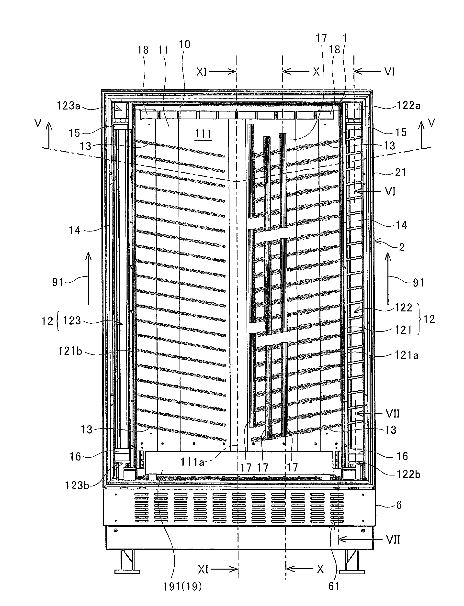
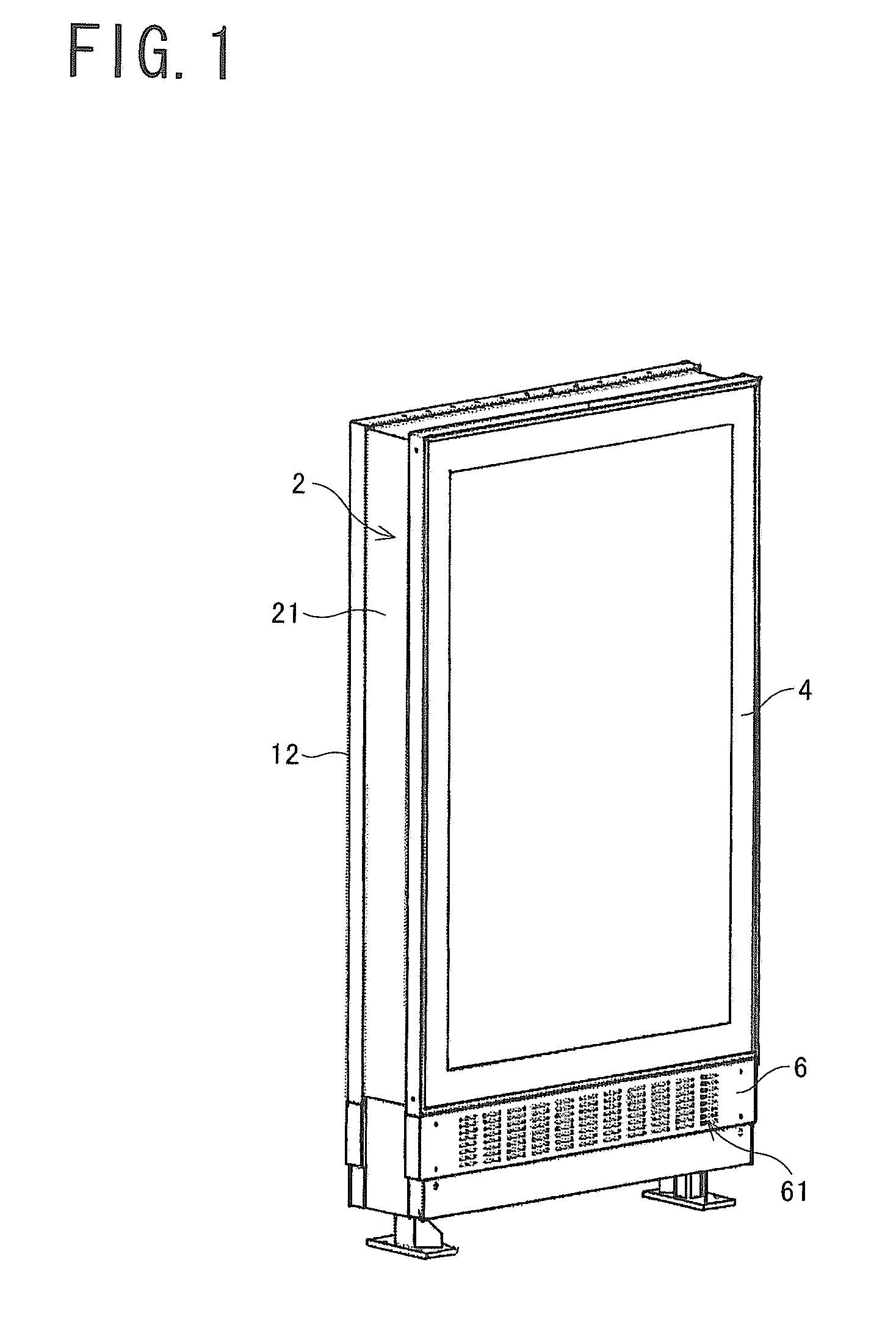
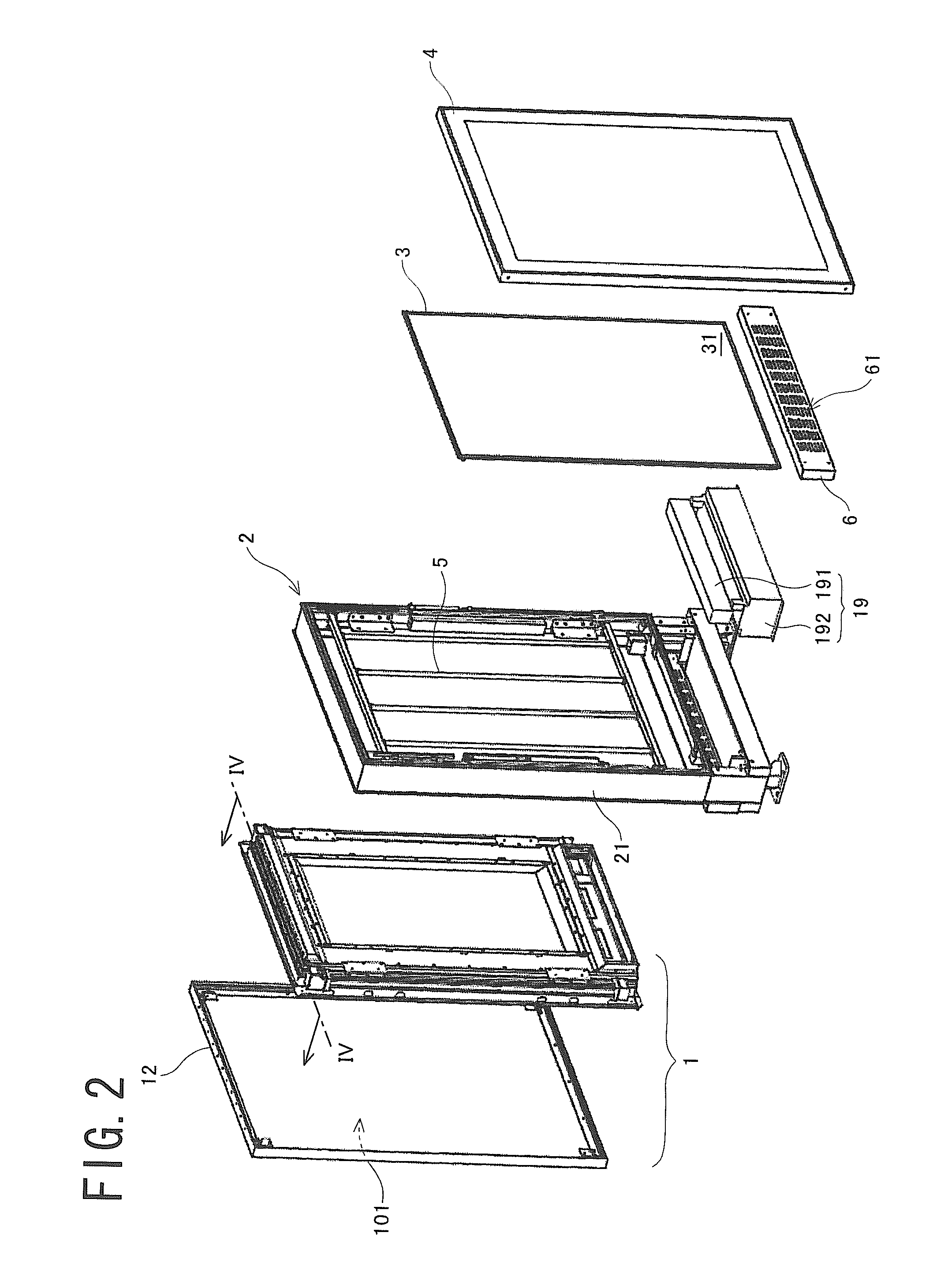
[0026]An image display system has a flat rectangular solid-shaped appearance as shown in FIG. 1, and comprises a display apparatus 1, a base 2, a backboard 3, a cover 4, fluorescent light fittings 5 and an aeration plate 6 as shown in FIG. 2. Each element is described in detail below.

[0027]The display apparatus 1 can display a video on a screen 101, and has a liquid crystal display as described later. The detail of the display apparatus 1 is described later in section 2“DISPLAY APPARATUS”.

[0028]The base 2 includes a frame member 21. The member 21 has a structure that can insert the display apparatus 1 and the backboard 3 therein. When the apparatus 1 is attached to the base 2, the apparatus 1 is fitted in the member 21 with its screen (101) facing opposite to the backboard 3.

[0029]The fluorescent light fitting...


PUM


Abstract

A display apparatus includes a liquid crystal display having a display panel, a housing, and a plurality of heat pipes. The housing has a sealing part and has aeration paths. The sealing part seals the display panel to box the display panel therein, while making a display screen of the display panel viewable from outside. The aeration paths are arranged outside the sealing part and communicate with the outside of the housing. The heat pipes extend from a rear surface of the display panel to the aeration paths.

Description

[0001]This application is a continuation application of Patent Cooperation Treaty Patent Application No. PCT / JP2009 / 057187 (filed on Apr. 8, 2009), which claims priority from Japanese patent application JP2008-145443 (filed on Jun. 3, 2008). All of which are hereby incorporated by reference herein.BACKGROUND OF THE INVENTION[0002]1. Field of the Invention[0003]The present invention relates to a display apparatus, and particularly to a display apparatus for outdoor installation.[0004]2. Description of Related Art[0005]Conventionally, flat-panel displays such as a liquid crystal display (LCD) (for example, JP2005-286987 A1) have been widely used as monitors for image displays. However, most of the conventional LCDs are designed for indoor installation, and they are not designed for protection from weather or dust. Therefore, it was difficult to install a conventional LCD outside permanently.[0006]However, in recent years, it has been desired to place LCDs permanently outdoors. This is...

Claims


Application Information

Patent Timeline
IPC IPC(8): H05K7/20
CPCH05K7/2099G09F9/35
Inventor NAKAMICHI, MASAYATAKAHASHI, SHOHEI
Owner SANYO ELECTRIC CO LTD
Why Eureka
Try Eureka