Light pen

Inactive Publication Date: 2011-03-31
CHUNGHWA PICTURE TUBES LTD
View PDF10 Cites 33 Cited by
  • Summary
  • Abstract
  • Description
  • Claims
  • Application Information

AI Technical Summary

Problems solved by technology

However, since the user needs to hold the light pen in mid-air, the said method usually makes the user incapable of inputting

Method used


Image

  • Light pen
  • Light pen
  • Light pen

Examples


Embodiment Construction

[0016]Certain terms are used throughout the description and following claims to refer to particular components. As one skilled in the art will appreciate, electronic equipment manufacturers may refer to a component by different names. This document does not intend to distinguish between components that differ in name but not function. In the following description and in the claims, the terms “include” and “comprise” are used in an open-ended fashion, and thus should be interpreted to mean “include, but not limited to . . . ”

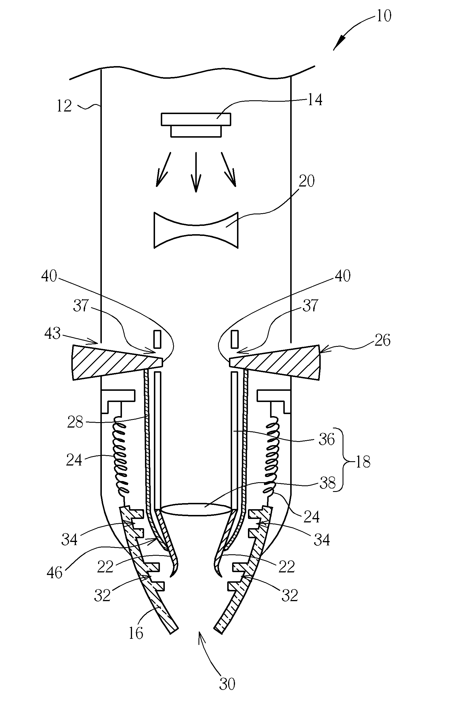
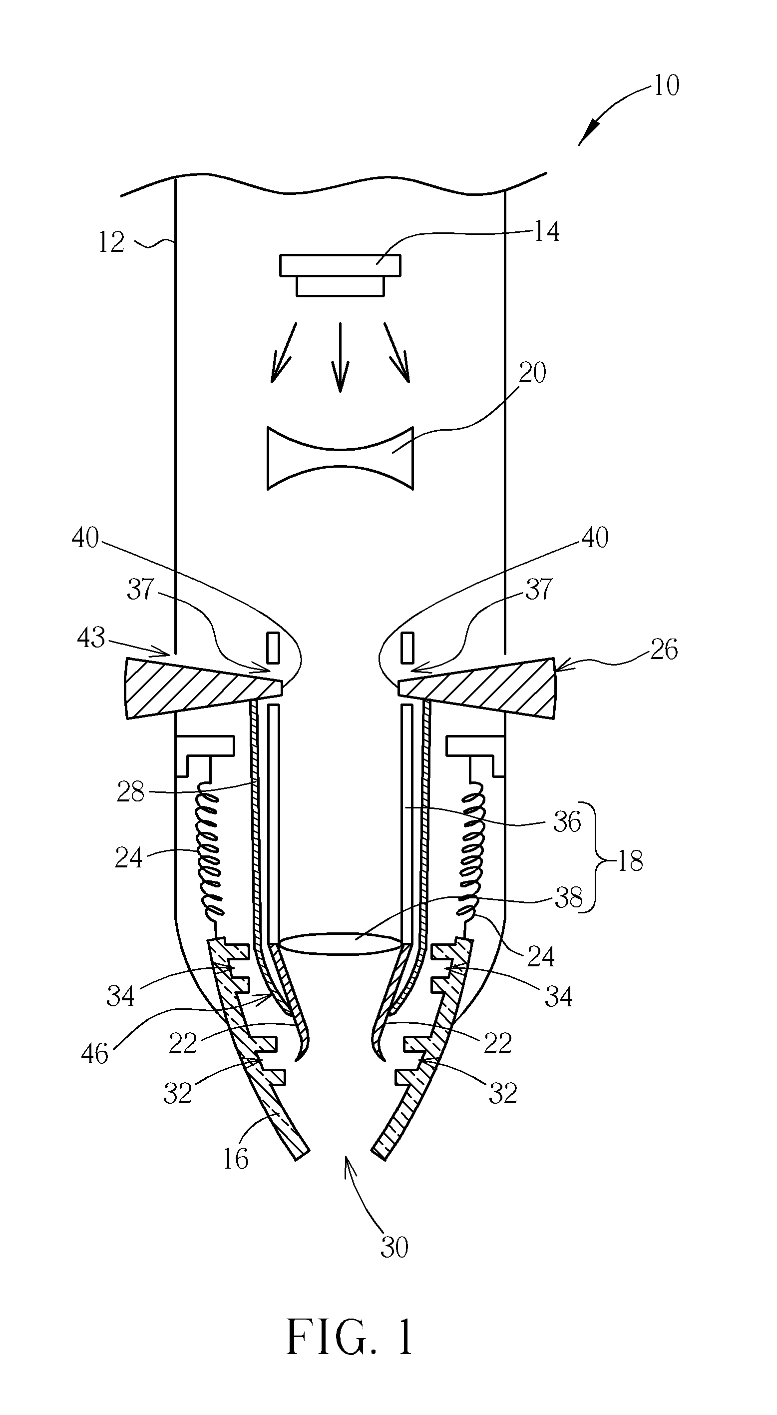
[0017]Please refer to FIG. 1, which is a cross-sectional diagram of a light pen 10 according to a preferred embodiment of the present invention. As shown in FIG. 1, the light pen 10 includes a case 12, a light source 14, a pen-nib structure 16, a first lens device 18, a second lens device 20, at least one elastic piece 22 (two shown in FIG. 1), at least one spring 24 (two shown in FIG. 1), a hollow knob 26, and a linkage pipe 28. The light source 14 is disposed i...


PUM


Abstract

A light pen includes a case, a light source, a pen-nib structure, a first lens device, an elastic piece, a hollow knob, and a linkage pipe. The pen-nib structure is disposed through the case. The first lens device is disposed between the light source and the pen-nib structure. The elastic piece is connected to the first lens device. The hollow knob rotatably sheathes the first lens device. The linkage pipe sheathes the first lens device and is connected to the hollow knob for driving the elastic piece to move away from the pen-nib structure when the hollow knob rotates to a first position, so that the pen-nib structure can move relative to the case. The linkage pipe is further used for being separate from the elastic piece when the hollow knob rotates to a second position, so that the elastic piece can be engaged with the pen-nib structure.

Description

BACKGROUND OF THE INVENTION[0001]1. Field of the Invention[0002]The present invention relates to a light pen, and more specifically, to a light pen capable of adjusting a beam area of a light source projected on an optical touch panel.[0003]2. Description of the Prior Art[0004]In general, a beam projected by a light pen is usually utilized as input of photo signals to a conventional optical touch panel, and light sensing elements disposed inside the optical touch panel are utilized for sensing the said photo signals. As far as input of X-axis and Y-axis information to the optical touch panel is concerned, the optical touch panel utilizes photo TFTs (Thin Film Transistors) disposed therein to determine locations of the photo signals by transforming the photo signals into corresponding photo currents, so that a user can perform X-axis and Y-axis operations on the optical touch panel (e.g. moving a cursor, or rolling a scroll). On the other hand, for input of Z-axis information to the ...

Claims


Application Information

Patent Timeline
IPC IPC(8): H01S3/00B43K29/10H01L33/00
CPCG06F3/03545G06F2203/04105G06F2203/04101
Inventor WANG, YIN
Owner CHUNGHWA PICTURE TUBES LTD
Why Eureka
Try Eureka