
Method and device for recording a projection dataset of an object using a plurality of x-ray sources

Active Publication Date: 2011-03-31
SIEMENS HEALTHCARE GMBH
View PDF5 Cites 20 Cited by
  • Summary
  • Abstract
  • Description
  • Claims
  • Application Information

AI Technical Summary

Benefits of technology

[0005]It is the object of the present invention to provide a method for recording a projection dataset of an object to be recorded which permits a maximally artifact-free and rapid reconstruction of a projection image dataset into a 3D image; a further object of the invention is to provide an X-ray device that is suitable for performing the method.
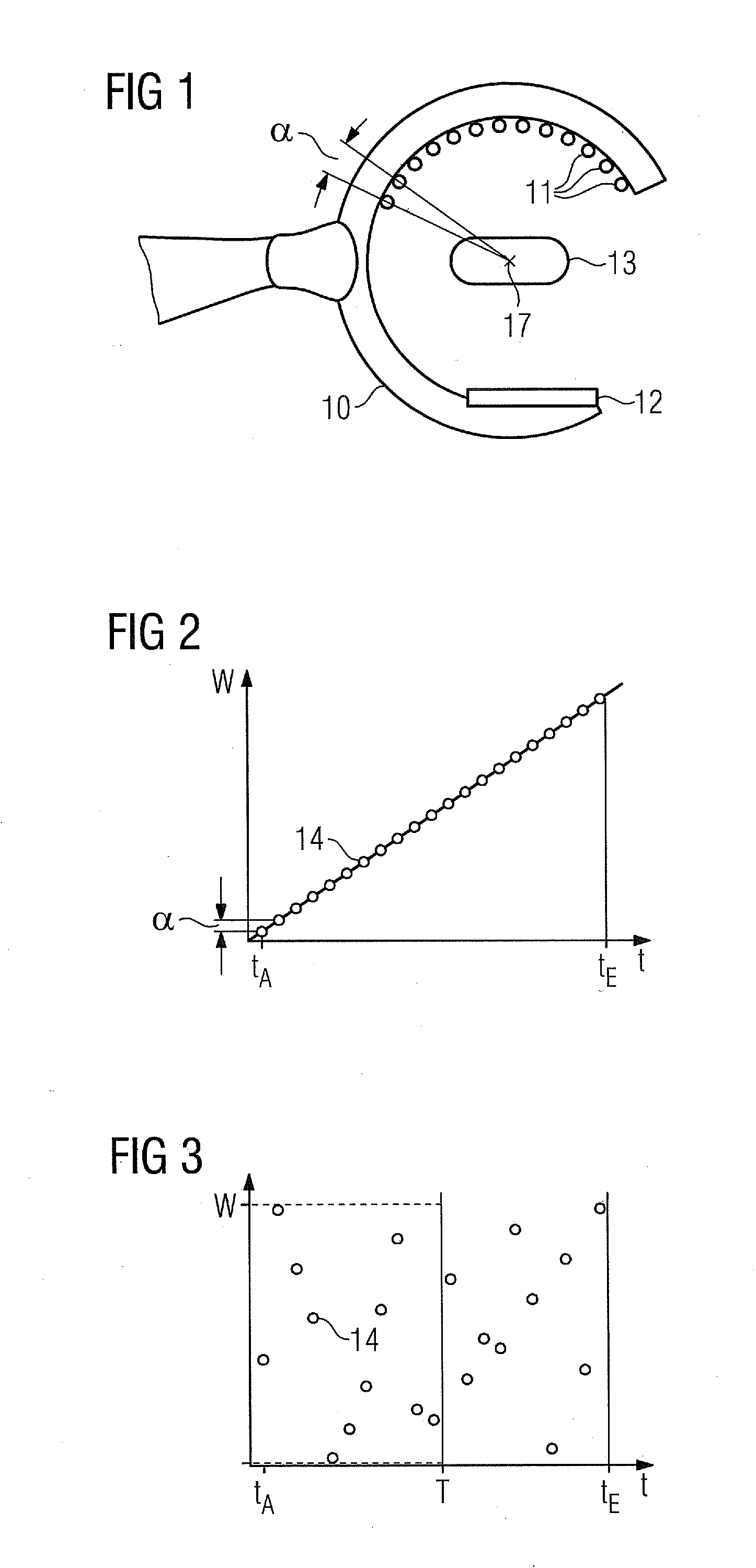
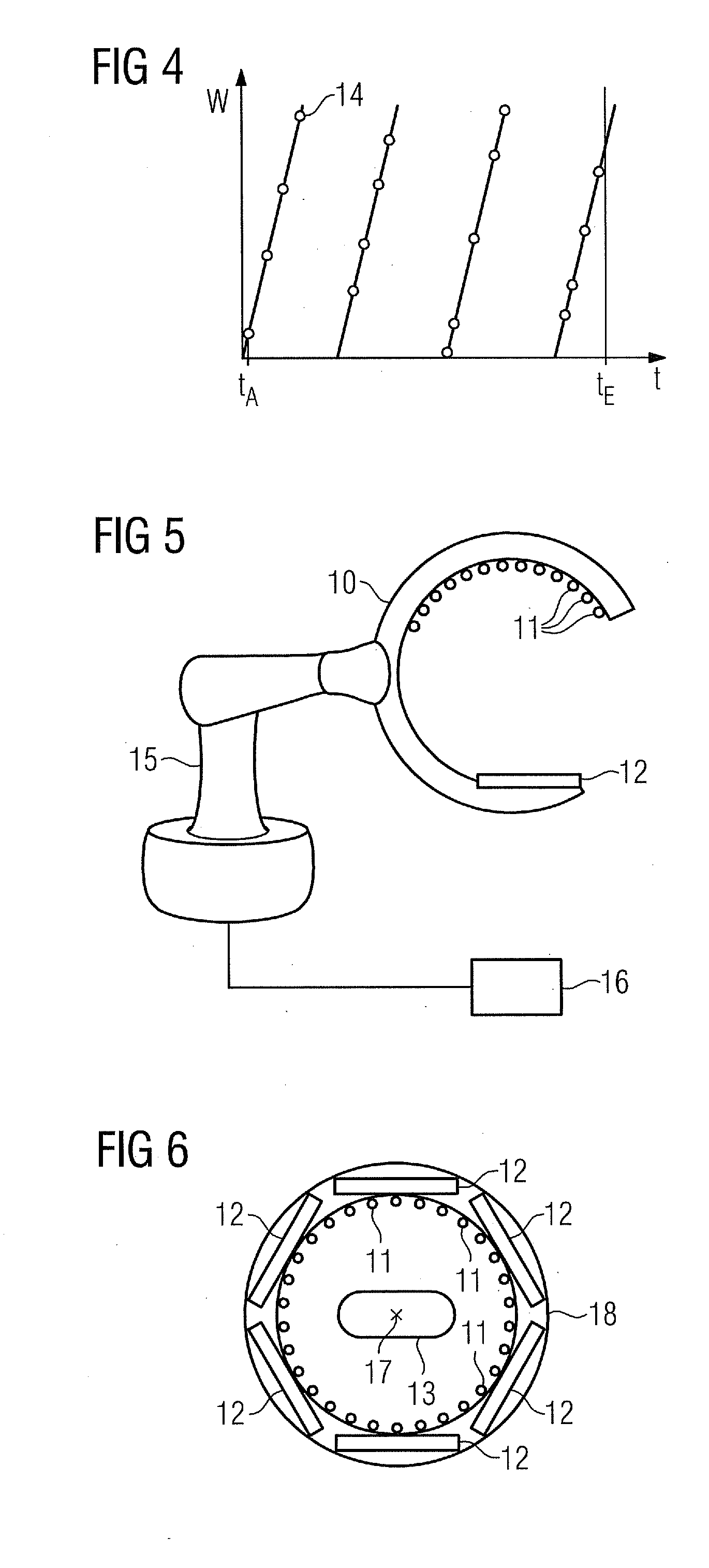
[0007]The inventive method for recording a projection dataset of a object to be recorded using a plurality of X-ray sources, which X-ray sources are spaced apart from one another on average by an angle α relative to an isocenter, comprises the following steps: recording a plurality of projection images from different recording directions in succession while activating the corresponding X-ray sources, two X-ray sources activated in succession having a spacing of at least 2 α relative to the isocenter. No mechanical movements of the recording system are necessary in the case of the inventive method, so considerably fewer motion artifacts are produced than in the case of rotating systems. Furthermore, reconstructions can be performed already prior to a completed total recording of all the projection images of the projection dataset, with the result that a preliminary 3D image can already be available very quickly. This is possible owing to the fact that the projection recordings are not carried out one after another in ascending order in every possible recording direction, but rather that at most every second recording direction is used in direct succession so that a general overview over the entire range of recording directions is available much quicker.

Problems solved by technology

Problems with this method are, for example, that movements during the recording create artifacts, and that a useful reconstruction is available only after the recording trajectory has been terminated completely.
The problem of cardiac movements is dealt with by means of ECG gating, for example, though this leads in some cases to extended recording times, since the movement of the X-ray source cannot be stopped during the unwanted cardiac phases.

Method used


Image

  • Method and device for recording a projection dataset of an object using a plurality of x-ray sources
  • Method and device for recording a projection dataset of an object using a plurality of x-ray sources
  • Method and device for recording a projection dataset of an object using a plurality of x-ray sources

Examples


Embodiment Construction

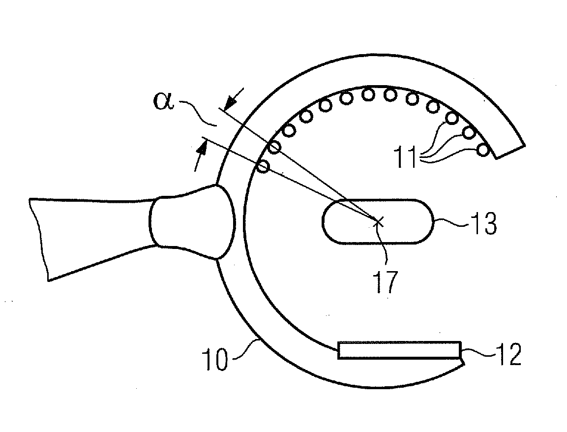
[0023]FIG. 1 shows a detail from an X-ray system according to the invention having a C-arm 10 on which are mounted an X-ray detector and a plurality of X-ray emitters 11. In this case the X-ray emitters 11 are arranged in the circumferential direction along the C-arm 10 and are spaced apart from one another on average by an angle α relative to an isocenter, for example the center point 17 of the C-arm. The isocenter is a fixed reference point and can be defined, for example, as the point around which the C-arm would rotate if it were to be necessary to perform a mechanical movement for the purpose of recording the projection images from different recording directions. On average, in this context, means that the spacings do not have to match precisely for each X-ray source.

[0024]The X-ray emitters 11 are arranged for example in the form of a linear array on the C-arm and are all aligned in such a way that the X-ray beam generated by them is concentrated on the X-ray detector 12. When...


PUM


Abstract

A method for recording a projection dataset of a object to be recorded using a plurality of X-ray sources is provided, which X-ray sources are spaced apart from one another on average by an angle α relative to an isocenter. A plurality of projection images from different recording directions are recorded in succession while activating the corresponding X-ray sources. Two X-ray sources are activated in succession having a spacing of at least 2 α relative to the isocenter.

Description

CROSS REFERENCE TO RELATED APPLICATIONS[0001]This application claims priority of German application No. 10 2009 043 420.8 filed Sep. 29, 2009, which is incorporated by reference herein in its entirety.FIELD OF THE INVENTION[0002]The invention relates to a method for recording a projection dataset of an object to be recorded and to a device for performing such a method.BACKGROUND OF THE INVENTION[0003]In 3D X-ray imaging, a sequence of two-dimensional projection images which have been acquired from different recording directions in relation to the object to be recorded is converted into a 3D representation of the object density by means of a tomosynthesis or CT algorithm. The achievable image quality of the 3D image is dependent to a significant degree on the type of data acquisition, in particular on the recording directions from which the projection images were recorded and on the associated recording times. In the prior art the different recording directions are generally arrived ...

Claims


Application Information

Patent Timeline
IPC IPC(8): H05G1/70
CPCA61B6/032A61B6/4007A61B6/4014H01J2235/062A61B6/503A61B6/541A61B6/466
Inventor BOESE, JANDENNERLEIN, FRANK
Owner SIEMENS HEALTHCARE GMBH
Learn More