Lubricant applicator, image forming apparatus, and method of mounting lubricant applicator

a technology of lubricant applicators and forming apparatus, which is applied in the direction of manual lubrication, instruments, manufacturing tools, etc., can solve the problems of inability to visually confirm the mounting of the compression spring, the inability to achieve cleaning performance, and the improvement of the product li

Inactive Publication Date: 2011-03-31
RICOH KK
View PDF17 Cites 17 Cited by
  • Summary
  • Abstract
  • Description
  • Claims
  • Application Information

AI Technical Summary

Benefits of technology

[0012]It is an object of the present invention to at lea...

Problems solved by technology

For this reason, the quantity of application of the lubricant onto the image carrier varies from the beginning over time, so that there is a possibility that the above effects, such as improvement in a cleaning performance, improvement in a product life, and improvement in a transfer performance, may not be obtained over time.
However, many of compression springs of which spring constant is set to a low value have a long free length compared with a length that is required in an actual use, and the diameter of wire of the spring is thin, consequently, there is a disadvantage that buckling tends to occur in the spring due to a pressure applied to the spring when the spring is mounted.
Furthermore, even when buckling occurs in the compression spring 7, it cannot be visually confirmed to mount the compression spring 7 again.
Furthermore, even when buckling occurs in the compression spring 7, it cannot be visu...

Method used


Image

  • Lubricant applicator, image forming apparatus, and method of mounting lubricant applicator
  • Lubricant applicator, image forming apparatus, and method of mounting lubricant applicator
  • Lubricant applicator, image forming apparatus, and method of mounting lubricant applicator

Examples


Embodiment Construction

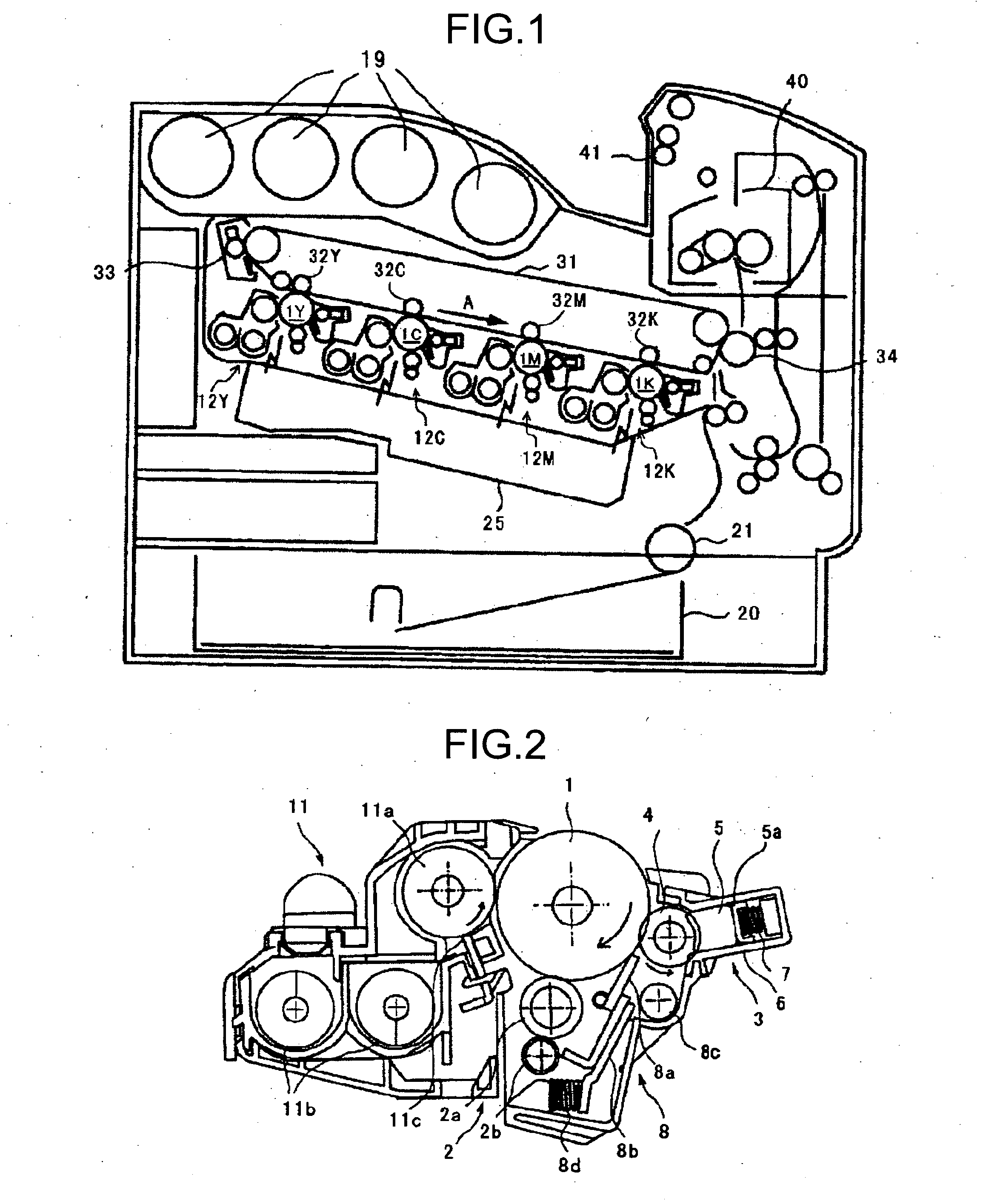
[0033]An embodiment that the present invention is applied to an image forming apparatus is explained below. First of all, a configuration and operation of an image forming. apparatus according to the embodiment is explained below.

[0034]FIG. 1 is a schematic configuration diagram of the whole image forming apparatus according to the embodiment. The image forming apparatus shown in FIG. 1 is a color image forming apparatus that forms an image from toners of four colors, namely, yellow (Y), cyan (C), magenta (M), and black (K). The image forming apparatus includes four image forming units 12Y, C, M, and K that form respective colors, and the image forming units are arranged along an intermediate transfer belt 31 of which surface moves in the direction of an arrow A in the figure. The image forming units 12Y, C, M, and K includes photosensitive elements 1Y, C, M, and K, respectively, each of which is an image carrier.

[0035]In the inner side of the intermediate transfer belt 31, primary ...


PUM

PropertyMeasurementUnit
Shapeaaaaaaaaaa
Elasticityaaaaaaaaaa

Abstract

A lubricant applicator includes: a lubricant application unit that is arranged so as to be in contact with a surface of an image carrier, scrapes a solid lubricant, and applies the solid lubricant onto the surface of the image carrier while moving a surface of the lubricant application unit; a lubricant holding member that holds the solid lubricant; and a lubricant biasing unit that biases the solid lubricant against the lubricant application unit. The lubricant biasing unit is housed in a housing under a state that one end of the lubricant biasing unit is held by the lubricant holding member so that a position of the one end of the lubricant biasing unit is restricted, and another end of the lubricant biasing unit is held by a biasing-unit holding member that is provided to restrict a position of the another end of the lubricant biasing unit.

Description

CROSS-REFERENCE TO RELATED APPLICATIONS[0001]The present application claims priority to and incorporates by reference the entire contents of Japanese Patent Application No. 2009-222521 filed in Japan on Sep. 28, 2009. The present document incorporates by reference the entire contents of Japanese application, 2008-254132 filed in Japan on Sep. 30, 2008.BACKGROUND OF THE INVENTION[0002]1. Field of the Invention[0003]The present invention relates to an image forming apparatus, such as a copier, a facsimile, and a printer; and a lubricant applicator that is configured to be used for the image forming apparatus.[0004]2. Description of the Related Art[0005]Conventionally, a lubricant applicator that applies a lubricant onto a surface of an image carrier is known to aim improvement in a cleaning performance, improvement in a product life, and improvement in a transfer performance of a photosensitive element and an intermediate transfer belt each of which is an image carrier (for example, J...

Claims


Application Information

Patent Timeline
IPC IPC(8): G03G21/00F16N15/00B23P19/00
CPCY10T29/49826G03G21/00
Inventor ARAI, YUJIAMEMIYA, KENKOIKE, TOSHIOOKAMOTO, MICHIYAIWASAKI, TAKUMANAGASHIMA, HIROYUKIITOH, FUMIHITOONO, HIROSHISHAKUTO, MASAHIKOYOSHINO, KAORUHATORI, SATOSHIAZEYANAGI, YUTA
Owner RICOH KK
Why Eureka
Try Eureka