Method and Apparatus of ATE IC Scan Test Using FPGA-Based System

a technology of fpga-based system and ic scan test, which is applied in the direction of detecting faulty computer hardware, error detection/correction, instruments, etc., can solve the problem of insufficient resources at the ate system level, affecting and increasing the overall cost of the test system

Active Publication Date: 2011-03-31
INTEGRATED DEVICE TECH INC
View PDF10 Cites 46 Cited by
  • Summary
  • Abstract
  • Description
  • Claims
  • Application Information

AI Technical Summary

Benefits of technology

[0008]An apparatus and a method for enhancing an automated test equipment (ATE), are presented. The apparatus comprises a test load board that mounts a plurality of devices to be tested (DUTs), and a daughter card communicating with the test board and the ATE, testing each of the plurality of devices, and providing test results to the ATE. The method comprises mounting a plurality of devices to be tested on the test load board, using the daughter card to communicate with the test board and the ATE, and using the daughter card for testing each one of the plurality of DUTs, providing test results to the ATE. Also provided is a system to perform automated tests of integrated chips, comprising an ATE scan test unit, an off-load tester resource coupled to the ATE scan test unit, a processor executing commands to control the ATE unit and the off-load tester resource.

Problems solved by technology

In current applications for the integrated circuit (IC) industry, with the demand for higher throughput of devices, state-of-the-art automated test equipment ATE presents a resource limitation problem.
The insufficiency of these resources at the ATE system level is translated into a production test throughput limitation due to the inability of state-of-the-art ATEs to test multiple devices on a single device under test (DUT) board.
This approach unduly increases the overall cost of the test system and drives up the cost of production.
The loose timing requirements imposed by these systems have an adverse effect on the overall speed of the testing protocol, and even on the accuracy of the results.

Method used


Image

  • Method and Apparatus of ATE IC Scan Test Using FPGA-Based System
  • Method and Apparatus of ATE IC Scan Test Using FPGA-Based System
  • Method and Apparatus of ATE IC Scan Test Using FPGA-Based System

Examples


Embodiment Construction

[0025]Scan test is the most popular design for test (DFT) methodology and is often implemented in register transfer level (RTL) design. Stuck-at-fault, DSM (at-speed) are common scan technologies for capturing manufacturing defects in IC chips. Normally, a scan vector is generated by an automated test pattern generator (ATPG) tool with a standard file format (e.g. WGL, STIL). Depending on device function, feature design and test coverage, the scan vector size can vary. More logic gate implementation and higher error coverage will naturally increase the scan vector size, imposing a higher demand on the memory resources of the ATE system. For scan test program development, scan test vectors are converted into ATE format with timing and level setup. The tester will load scan vectors into vector memory for testing. Therefore, the scan vectors memory size is one key factor for ATE program.

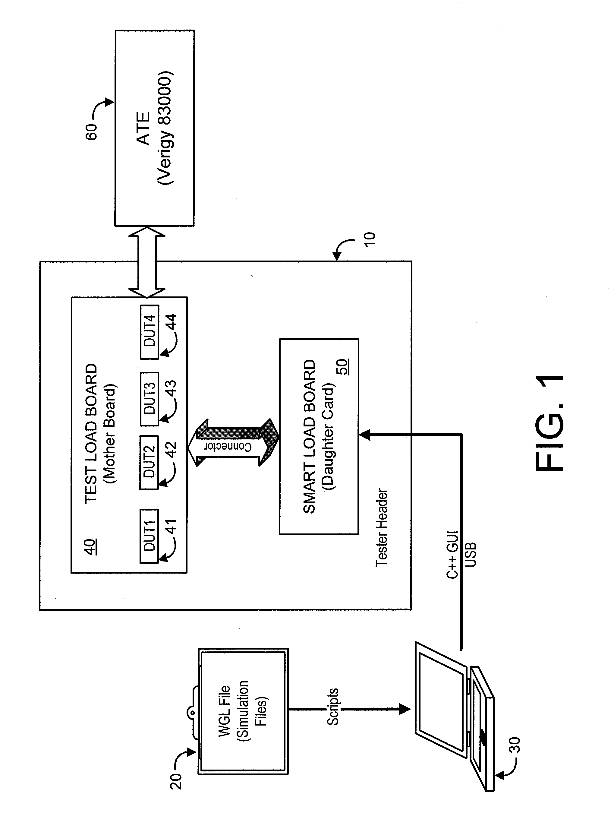
[0026]The Verigy (Agilent sold tester to Verigy) 83000 / 93000 ATE system is one test platform commonl...


PUM


Abstract

An apparatus and a method for enhancing the use of automated test equipment (ATE), are presented. The apparatus comprises a test load board that mounts a plurality of devices to be tested (DUTs), and a daughter card communicating with the test board and the ATE, testing each of the plurality of devices, and providing test results to the ATE. The method comprises mounting a plurality of devices to be tested on the test load board, using the daughter card to communicate with the test board and the ATE, and using the daughter card for testing each of the plurality of DUTs, providing test results to the ATE. Also provided is a system to perform automated tests of integrated chips, comprising an ATE scan test unit, an off-load tester resource coupled to the ATE scan test unit, a processor executing commands to control the ATE unit and the off-load tester resource.

Description

BACKGROUND[0001]1. Field of the Invention[0002]The embodiments described herein relate generally to the field of automated test equipment (ATE) and, more particularly, to test equipment that performs integrated circuit (IC) scan tests.[0003]2. Description of Related Art[0004]In current applications for the integrated circuit (IC) industry, with the demand for higher throughput of devices, state-of-the-art automated test equipment ATE presents a resource limitation problem. Two particular resources of relevance are scan vector memory and scan channels. The insufficiency of these resources at the ATE system level is translated into a production test throughput limitation due to the inability of state-of-the-art ATEs to test multiple devices on a single device under test (DUT) board.[0005]Traditionally in the semiconductor IC industry, to achieve scan test results that keep up with production demands, the solution is to increase ATE resources, such as acquiring more scan vector memory ...

Claims


Application Information

Patent Timeline
Patent Type & Authority Applications(United States)
IPC IPC(8): G01R31/3177G06F11/25
CPCG06F11/25G01R31/318563
Inventor XIA, YUVENTURA, DALERAMACHANDRAN, ASHOK
Owner INTEGRATED DEVICE TECH INC
Why Eureka
Try Eureka