Automatic external adjustable spool braking system

a brake system and automatic technology, applied in the direction of reels, applications, fishing, etc., can solve the problems of frequent backlash and adverse effects of centrifugal braking on casting distance, and achieve the effects of preventing backlash on casting distance, better brake control, and better distan

Inactive Publication Date: 2011-04-07
KIM HYUNKYU +1
View PDF27 Cites 11 Cited by
  • Summary
  • Abstract
  • Description
  • Claims
  • Application Information

AI Technical Summary

Benefits of technology

[0008]The result is better brake control to prevent backlash on casting and an ability to achieve better distance by reducing spool braking force when the spool rotation slows down, i.e., when the brake assembly returns to its original position by spring force.

Problems solved by technology

Backlash may frequently occur when the line-carrying spool is rotating at high velocities.
Centrifugal braking may have an adverse effect on casting distance.
Therefore, with the development of easily adjustable brake systems, many fishermen set the brake control to “free” when pitching, which could result in backlash.

Method used


Image

  • Automatic external adjustable spool braking system
  • Automatic external adjustable spool braking system
  • Automatic external adjustable spool braking system

Examples


Embodiment Construction

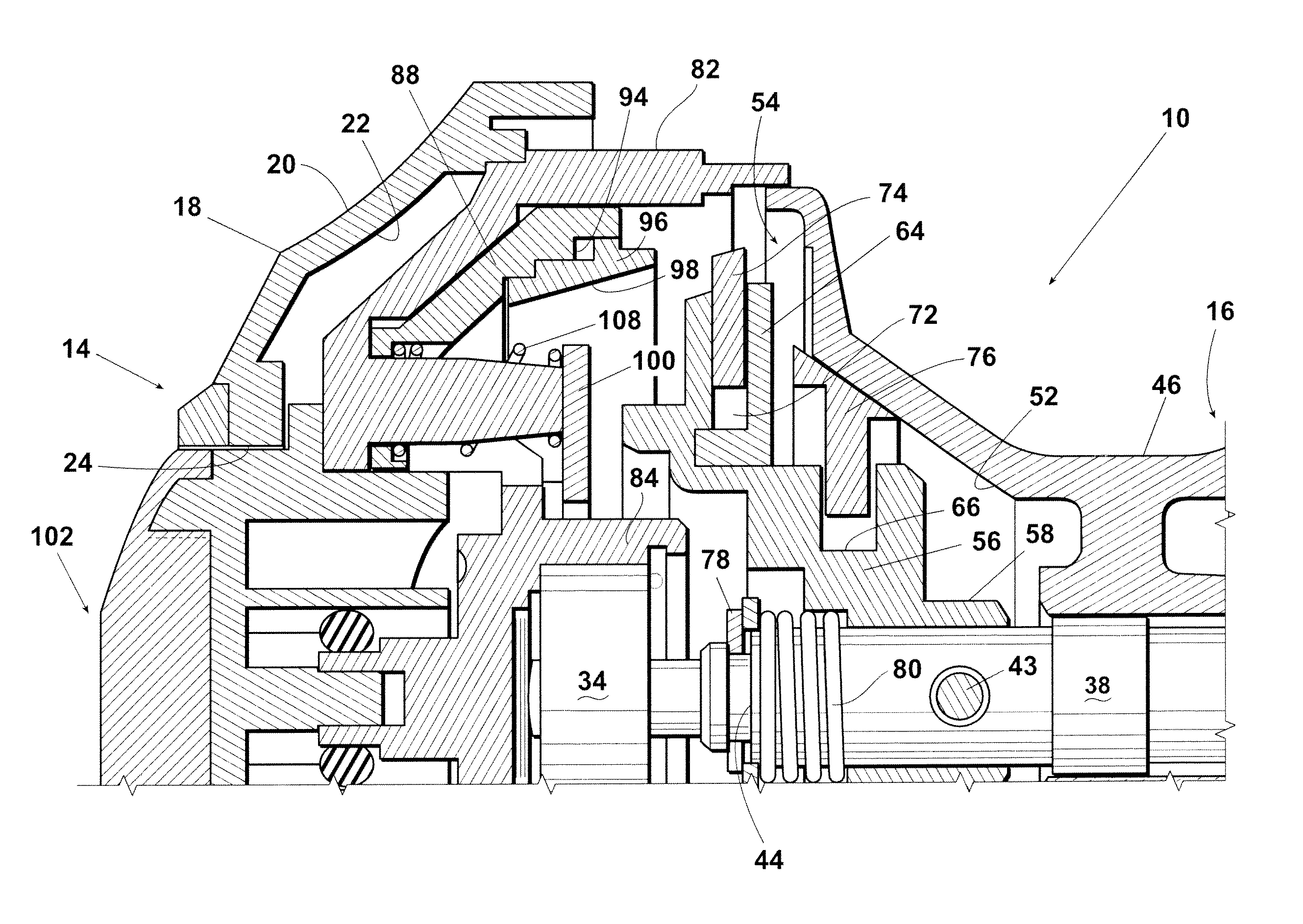
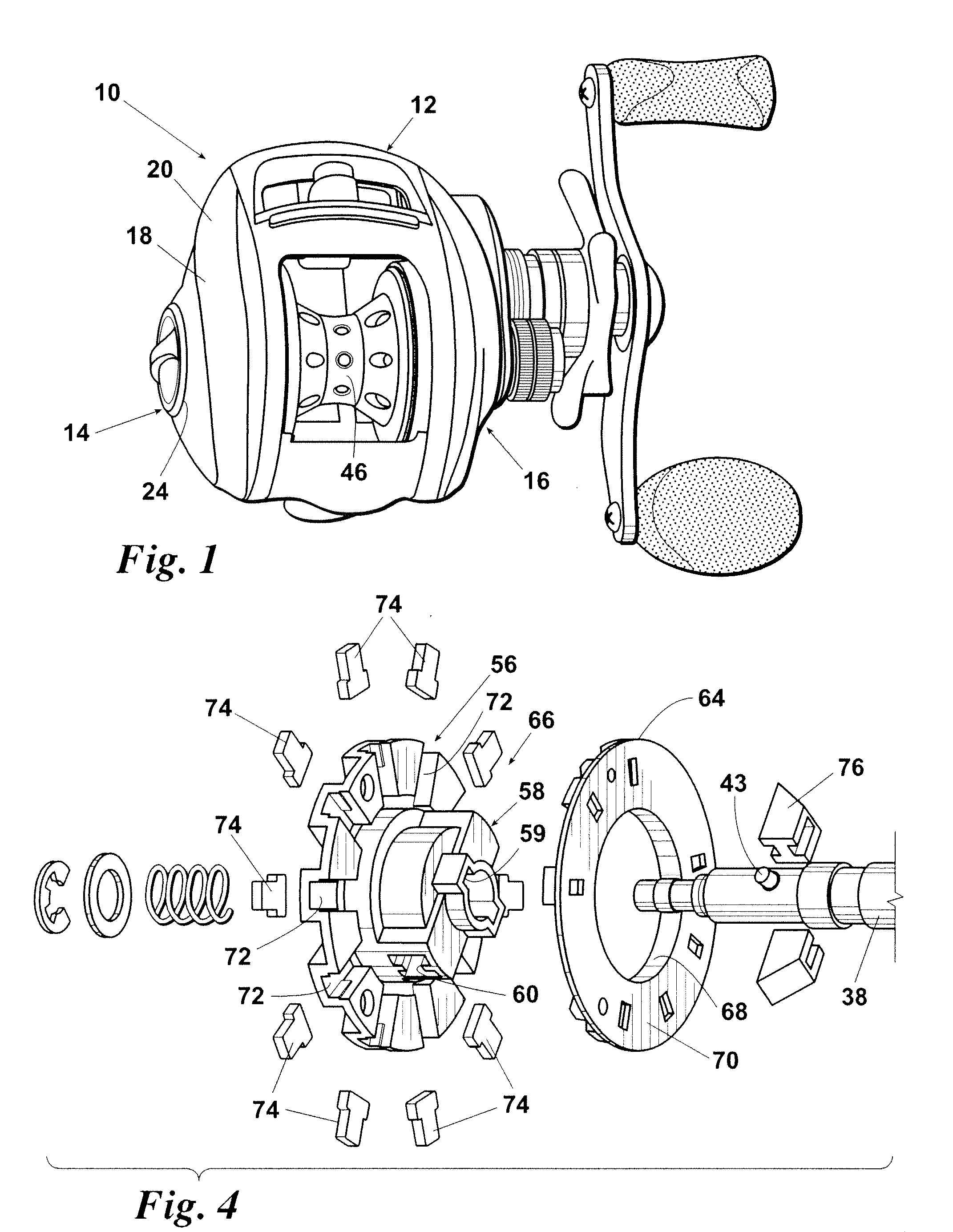
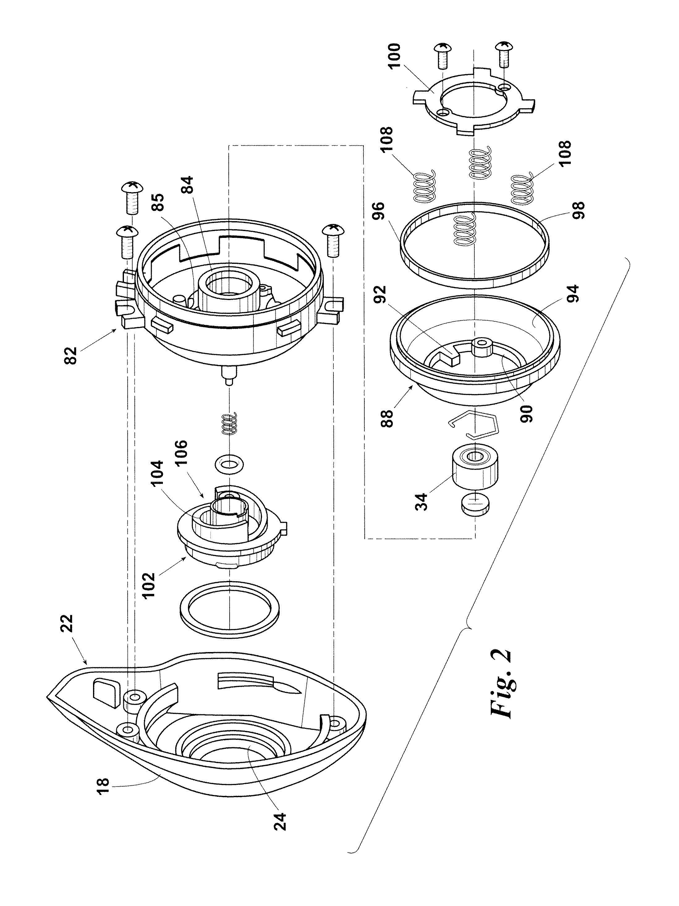
[0018]Shown in FIGS. 1-8 is a reel designated generally 10. Reel 10 includes frame 12 having palm side 14 and gear side 16. Palm side cover assembly 18 has outside surface 20 and inside surface 22. Inside surface 22 of palm side cover assembly 18 is affixed to palm side 14 of frame 12. Palm side cover assembly 18 defines dial orifice 24.

[0019]Crank shaft 26 (FIG. 3) is rotatably mounted within frame 12. Crank shaft 26 has a palm end 28 and a gear end 30. Pinion gear 32 is affixed to palm end 28 of crank shaft 26.

[0020]Spool shaft ball bearing 36 is mounted in gear side 16 of frame 12 for supporting gear end 40 of spool shaft 38. Spool shaft 38 has a gear end 40 and a palm end 42. Pin 43 protrudes from a side wall of spool shaft 38. Gear end 40 is supported by spool shaft bearing 36. Spool shaft 38 defines a clip receptacle 44 (FIGS. 6-8) proximate to palm end 42. Pin 43 protrudes from spool shaft 38.

[0021]Palm side spool shaft ball bearing 45 supports palm end 42 of spool shaft 38. ...


PUM


Abstract

In a fishing reel, in addition to an externally adjustable brake system, an automatic spool brake system adjusts spool braking action dependent upon spool rotation speed to provide brake control for preventing backlash and to achieve better casting distance by reducing spool braking force at low spool rotation speeds. A brake assembly has a plurality of brake shoes and speed adjust shoes and is slidably mounted on a spool shaft. An adjustable brake ring selectively engages the brake shoes to provide a braking action to the spool. A spring is provided for biasing the brake assembly away from the brake. Centrifugal force causes the speed adjust shoes to migrate outwardly in contact with a conical surface. The shoes impart an axial force to the brake assembly for moving the assembly towards the brake ring. At lower speeds, the spring pushes the brake assembly away from the brake ring.

Description

FIELD OF THE INVENTION[0001]The present invention relates to centrifugal brake systems on fishing reels and, more particularly, to an automatic brake system wherein braking action on the spool is dependent upon the rotation speed of the spool in addition to an infinitive external adjustment brake system.BACKGROUND OF THE INVENTION[0002]Centrifugal brake systems are commonly used on casting reels to prevent backlash. Backlash may frequently occur when the line-carrying spool is rotating at high velocities. Commonly, a brake mechanism is mounted on the spool for rotation therewith. The brake mechanism has an associated brake pad that is urged radially outwardly against a brake surface on the reel housing by centrifugal forces produced by the rotation of the spool.[0003]Centrifugal braking may have an adverse effect on casting distance. Therefore, with the development of easily adjustable brake systems, many fishermen set the brake control to “free” when pitching, which could result in...

Claims


Application Information

Patent Timeline
Patent Type & Authority Applications(United States)
IPC IPC(8): A01K89/033
CPCA01K89/033A01K89/01557A01K89/01931
Inventor KIM, HYUNKYUNAM, JUNGHYUN
Owner KIM HYUNKYU
Why Eureka
Try Eureka