Hydraulic brake solenoid valve protector

A hydraulic brake and solenoid valve technology, applied in the direction of brake actuators, valve devices, valve details, etc., can solve problems such as insufficient coil suction, solenoid valve coil burnout, solenoid valve core reset, etc., to prolong life Effect

Active Publication Date: 2019-07-30
GUANGXI LIUGONG MASCH CO LTD
View PDF6 Cites 0 Cited by
  • Summary
  • Abstract
  • Description
  • Claims
  • Application Information

AI Technical Summary

Problems solved by technology

[0003] The technical problem to be solved by the present invention is to provide a hydraulic brake solenoid valve protector, which can solve the problem that the existing solenoid valve in the brake controller works under high voltage for a long time, causing the temperature to rise As a result, the suction of the coil is insufficient, it is difficult to reset the valve core of the solenoid valve, and even the coil of the solenoid valve is burned out.

Method used


Image

  • Hydraulic brake solenoid valve protector

Examples


Embodiment Construction

[0011] The present invention will be described in further detail below in conjunction with accompanying drawing embodiment:

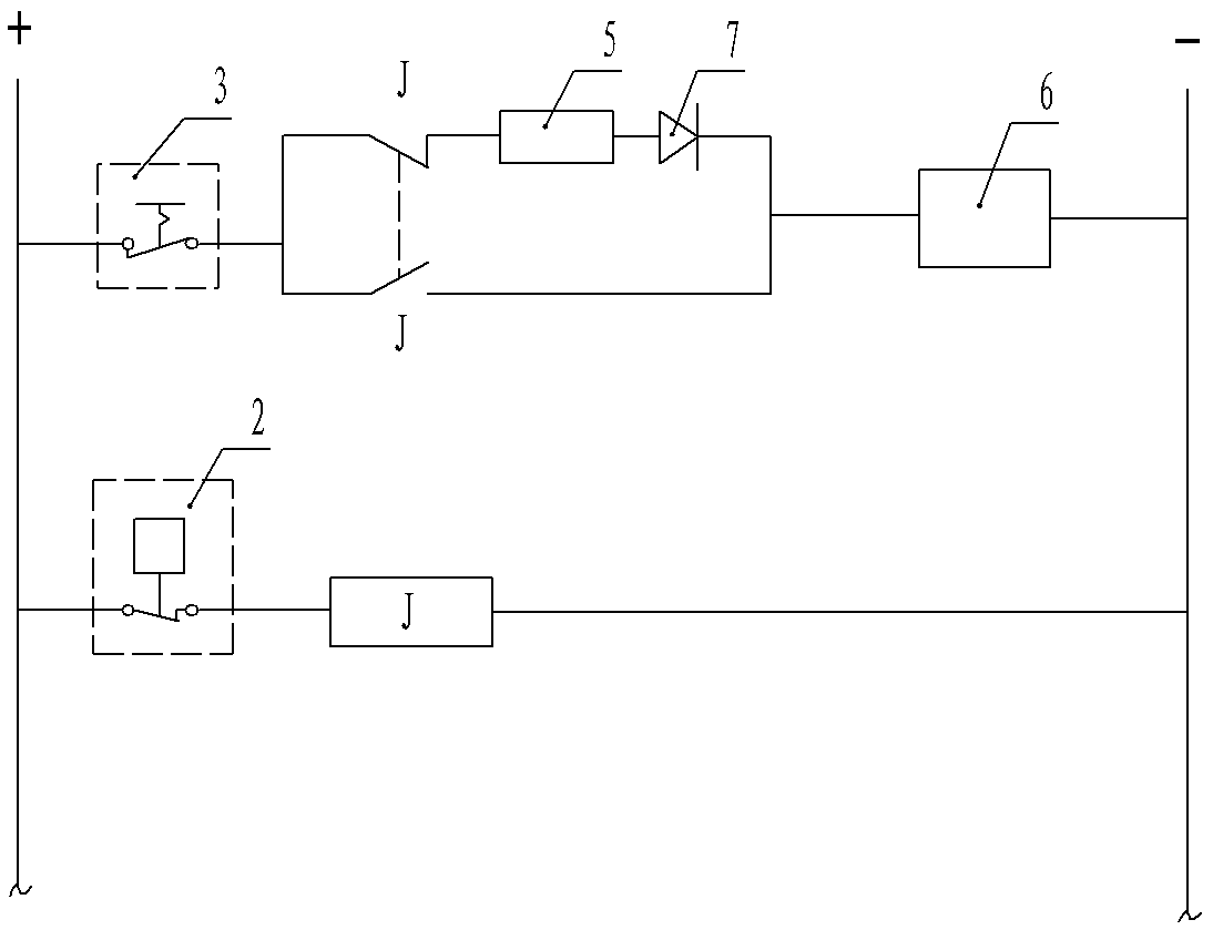
[0012] figure 1 The shown hydraulic brake solenoid valve protector includes a solenoid valve 6, and the coil of the solenoid valve 6 is connected to two power supply circuits through the parking brake switch 3 connected in series; one of the power supply circuits is connected in series with the dynamic disconnection contact of the relay J Point, current-limiting resistor 5 and light-emitting diode 7; another power supply circuit has a relay J moving contact in series; the relay J coil power supply circuit has a brake low-voltage switch 2 in series.

[0013] When the parking brake switch 3 is in the disconnected state and the solenoid valve 6 is in the de-energized state, the hydraulic brake takes effect at this moment, and the whole vehicle cannot walk and is in the parking brake state.

[0014] When the parking brake switch 3 is closed, the vehicle br...


PUM


Abstract

The invention discloses a hydraulic braking electromagnetic valve protector and belongs to the technical field of engineering machinery. The hydraulic braking electromagnetic valve protector comprises an electromagnetic valve connected with two power supply circuits, wherein one power supply circuit is serially connected with a moving break contact of a relay and a current-limiting resistor, the other power supply circuit is serially connected with a moving make contact of the relay, and a relay coil power supply circuit is serially connected with a braking low-voltage switch. The problem can be solved where since an existing electromagnetic valve in a braking controller operates for a long time under high voltage, temperature rise causes coil suction insufficiency to the valve, difficulty in resetting a valve core of the electromagnetic valve and even burnout of a coil of the electromagnetic valve.

Description

technical field [0001] The invention relates to the technical field of construction machinery, in particular to an electromagnetic valve protector used for hydraulic braking of construction machinery. Background technique [0002] In the hydraulic brake controller of construction machinery, the solenoid valve plays an important role. Its power-on or power-off directly controls the braking or releasing of the whole vehicle. Usually, when the vehicle is running after the brake is released, the solenoid valve is in the energized working state. At this time, the power supply of the solenoid valve is the same as the power supply of the vehicle's electrical equipment, and it is directly taken from the vehicle generator or battery, and its voltage follows the generator. Because the system voltage is generally around 28V after the whole machine is started, and the rated operating voltage of the solenoid valve is 24V, the coil temperature of the solenoid valve that has been working a...

Claims


Application Information

Patent Timeline
Patent Type & Authority Patents(China)
IPC IPC(8): F16D65/14F16K31/06F16K37/00F16D121/04F16D125/02
CPCF16D65/14F16D2121/04F16D2125/02F16K31/0675F16K37/0025
Inventor 廖平覃后嘉
Owner GUANGXI LIUGONG MASCH CO LTD
Why Eureka
Try Eureka