Inkjet recording apparatus

a recording apparatus and inkjet technology, applied in the direction of printing, inking apparatus, etc., can solve the problems of inability to investigate the issue of using a manifold having a sufficient thickness in order to achieve a large-volume circulation of ink, and achieve the effect of accurate ink circulation, low pressure loss, and low cos

Active Publication Date: 2011-04-07
FUJIFILM BUSINESS INNOVATION CORP +1
View PDF11 Cites 19 Cited by
  • Summary
  • Abstract
  • Description
  • Claims
  • Application Information

AI Technical Summary

Benefits of technology

[0031]According to this aspect of the present invention, since the pressure in the portion of each manifold where the flow speed is slowest is measured, then it is possible to obtain measurement values (pressure values) including little effect of dynamic pressure and even more accurate ink circulation can be achieved.
[0032]According to the present invention, the liquid supply manifold and the liquid collection manifold each have heights in the vertical direction whereby the gas getting mixed with the liquid can separate from the liquid in the vertical direction, the first bypass flow channel connecting these manifolds together is provided, and one end of the first bypass flow channel is connected to the upper side in the vertical direction (and desirably the upp

Problems solved by technology

Various technologies have been proposed for the recording heads of the inkjet recording apparatuses; however, in the line type apparatus, it is not practicable to form a single recording head that corresponds to the full width of the recording medium, as a single body, from a silicon wafer, glass, or the like, due to problems relating to the method of manufacture, the production yield, heat generation, cost, and the like.
In the inkjet recording apparatus, if bubbles are present in ink in flow channels inside the recording heads, then these can give ri

Method used


Image

  • Inkjet recording apparatus
  • Inkjet recording apparatus
  • Inkjet recording apparatus

Examples


first embodiment

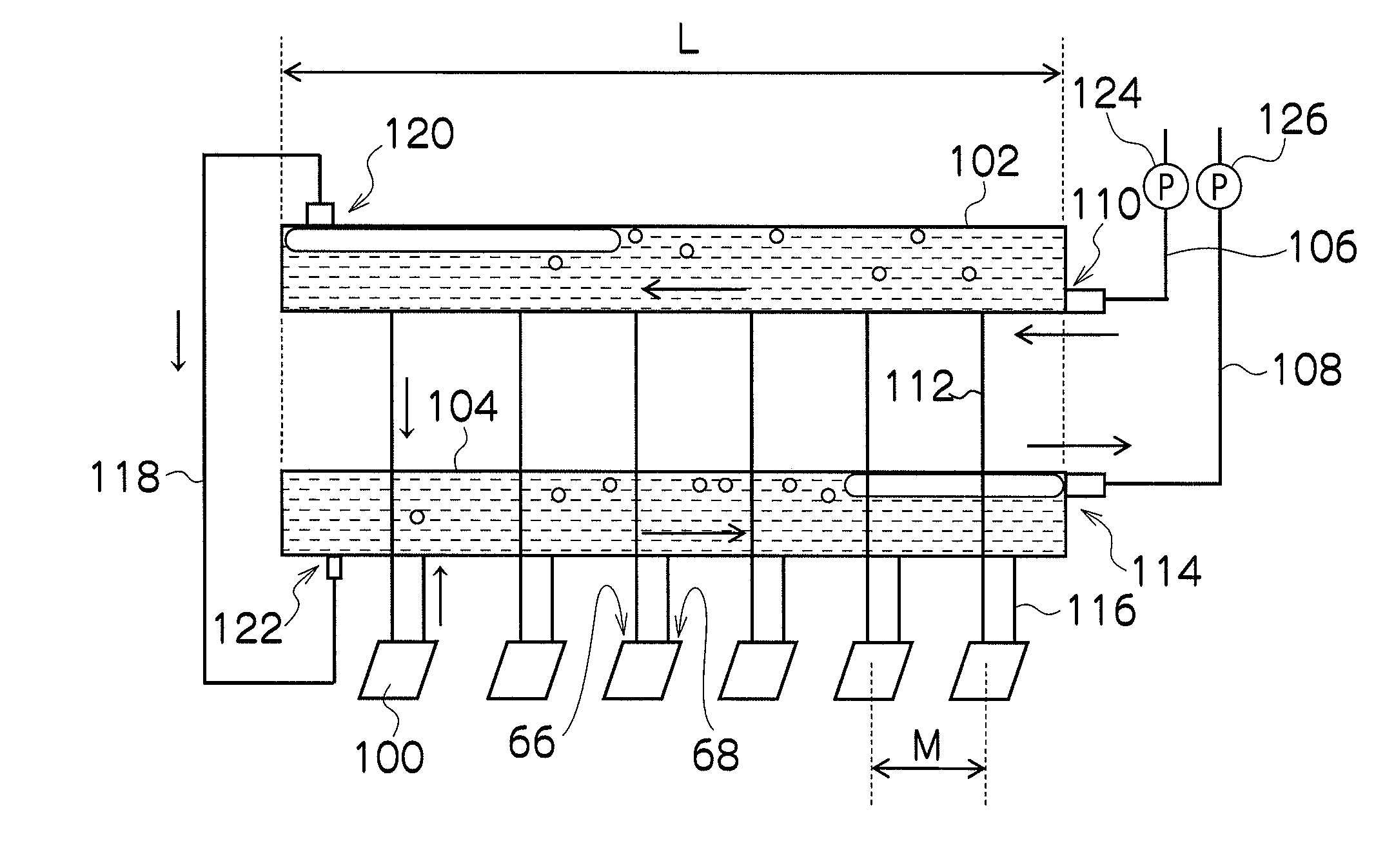
[0096]FIG. 6 is a schematic drawing showing the composition of the ink supply system according to a first embodiment of the present invention. In FIG. 6, in order to simplify the description, the ink supply system relating to one color only is depicted, and an inkjet recording apparatus of a plurality of colors is provided with a plurality of similar ink supply systems.

[0097]As shown in FIG. 6, the ink supply system of the inkjet recording apparatus 10 according to the present embodiment includes an ink supply manifold 102, which is a liquid chamber in which the ink supplied from the ink tank (not shown) to the respective head modules 100 is temporarily stored, and an ink collection manifold 104, which is a liquid chamber in which the ink collected from the head modules 100 to the ink tank is temporarily stored.

[0098]Each of the ink supply manifold 102 and the ink collection manifold 104 has a long thin shape having the lengthwise direction thereof along the direction in which the h...

second embodiment

[0116]FIG. 7 is a schematic drawing showing the composition of the ink supply system according to a second embodiment of the present invention. In FIG. 7, elements which are the same as or similar to those in FIG. 6 are denoted with the same reference numerals and description thereof is omitted here.

[0117]In the second embodiment, the bubble expulsion bypass flow channel 118 is provided with a valve (opening / closing valve) 130 as shown in FIG. 7. The opening and closing operation of the valve 130 is controlled by the system controller 72 shown in FIG. 5.

[0118]When performing the expulsion of bubbles, the system controller 72 implements control to open the valve 130, set the ink supply manifold 102 and the ink collection manifold 104 to a connected state through the bubble expulsion bypass flow channel 118, and move the bubbles in the ink supply manifold 102 to the ink collection manifold 104 through the bubble expulsion bypass flow channel 118. On the other hand, at other times (whe...

third embodiment

[0120]FIG. 8 is a schematic drawing showing the composition of the ink supply system according to a third embodiment of the present invention. In FIG. 8, elements which are the same as or similar to those in FIG. 6 or 7 are denoted with the same reference numerals and description thereof is omitted here.

[0121]If the ink supply manifold 102 and the ink collection manifold 104 are composed to have thick dimensions as in the respective embodiments described above, the ink flow rate in the manifolds becomes slow, the ink temperature varies due to exchange of heat with the surrounding air, and there is a concern that a difference will occur in the ink temperature between the head modules 100.

[0122]Hence, in the third embodiment, a circulation bypass flow channel 132, which is separate from the bubble expulsion bypass flow channel 118, is arranged between the ink supply manifold 102 and the ink collection manifold 104 as shown in FIG. 8. Thus, it is possible to circulate the ink directly ...


PUM


Abstract

The inkjet recording apparatus includes: a supply manifold having an inlet port to which a first main flow channel is connected, the liquid supplied from a tank through the first main flow channel being stored in the supply manifold, the supply manifold being connected to supply ports of head modules; a collection manifold having an outlet port to which a second main flow channel is connected, the liquid to be collected to the tank through the second main flow channel being stored in the collection manifold, the collection manifold being connected to discharge ports of the head modules; and a first bypass flow channel which connects the supply manifold to the collection manifold, wherein an end of the first bypass flow channel is connected to an upper side of an end of the supply manifold on a side opposite to a side where the inlet port is arranged.

Description

BACKGROUND OF THE INVENTION[0001]1. Field of the Invention[0002]The present invention relates to an inkjet recording apparatus, and more particularly to technology for circulating ink in a line head constituted of a plurality of head modules.[0003]2. Description of the Related Art[0004]An inkjet recording apparatus has a recording head (inkjet head) in which a plurality of nozzles are arranged on an ejection face, and records an image on a recording medium by ejecting ink droplets from the nozzles while moving the recording head and the recording medium relatively to each other. The ink ejection method of the recording head includes a piezoelectric method, which ejects an ink droplet from a nozzle by applying pressure to the ink inside a pressure chamber using the displacement of a piezoelectric element, and a thermal method, which ejects an ink droplet from a nozzle by means of the pressure generated when bubbles are produced inside a pressure chamber due to thermal energy produced...

Claims


Application Information

Patent Timeline
IPC IPC(8): B41J2/19
CPCB41J2/14233B41J2/155B41J2/19B41J2/18B41J2202/07B41J2202/12B41J2202/20B41J2002/14459
Inventor SHIBATA, HIROSHIKADOMATSU, TETSUZOKATAOKA, MASAKIMURAKAMI, ATSUSHI
Owner FUJIFILM BUSINESS INNOVATION CORP
Why Eureka
Try Eureka