
T-bar mounting system

a technology of mounting system and t-bar, which is applied in the direction of washstands, scaffold accessories, light support devices, etc., can solve the problem of not only difficult tasks

Active Publication Date: 2011-04-07
SIGNIFY NORTH AMERICA CORP
View PDF99 Cites 57 Cited by
  • Summary
  • Abstract
  • Description
  • Claims
  • Application Information

AI Technical Summary

Benefits of technology

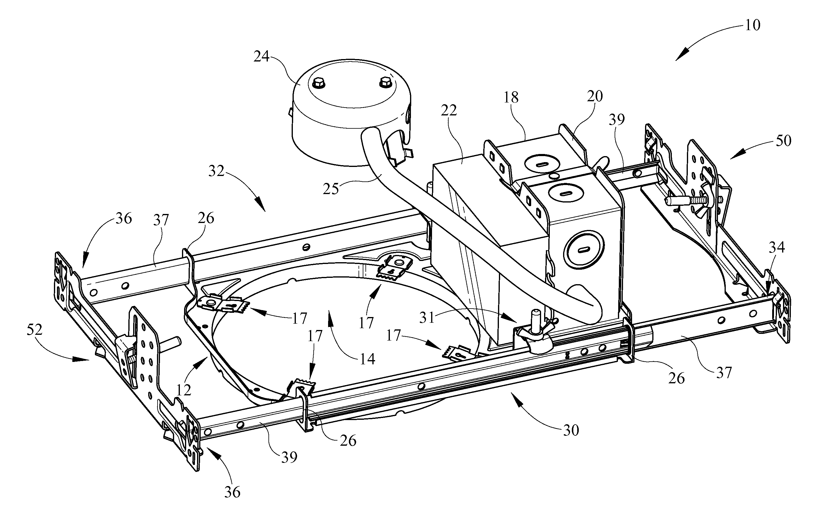
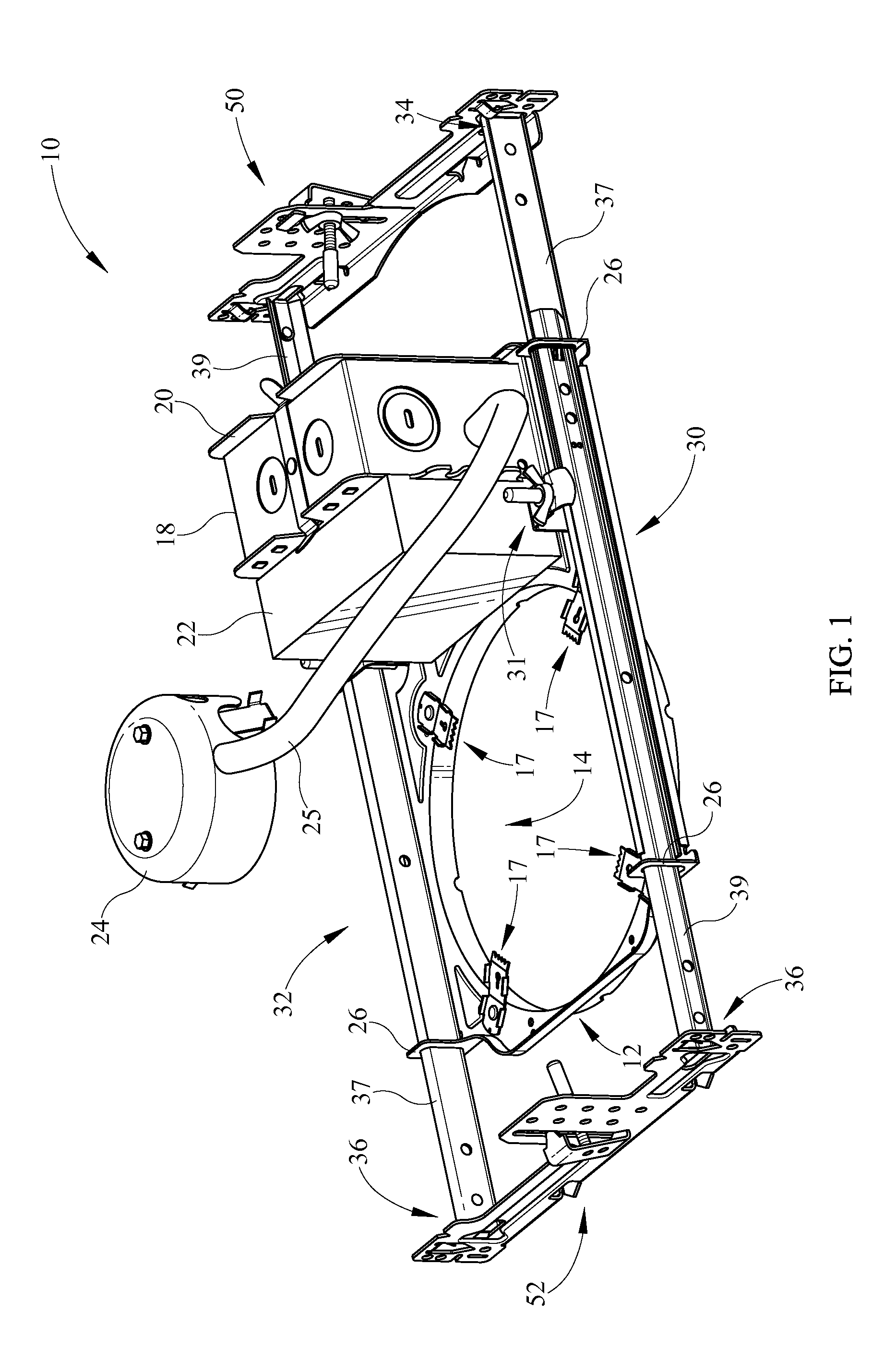
[0024]A recessed light mounting assembly comprises a frame having a finger, the finger having an opening for slidably positioning a hanger bar assembly, the hanger bar assembly comprises a first hanger bar slidably receiving a second hanger bar, the opening having a rolled edge defining an eyelet providing smooth sliding of the frame relative to the hanger bar assembly.

Problems solved by technology

Such activities are difficult in and of themselves, however, when working above the ceiling level on a ladder, the task is not only difficult, but may be unsafe.

Method used


Image

  • T-bar mounting system
  • T-bar mounting system
  • T-bar mounting system

Examples


Embodiment Construction

[0046]It should be understood that the invention is not limited in its application to the details of construction and the arrangement of components set forth in the following description or illustrated in the drawings. The invention is capable of other embodiments and of being practiced or of being carried out in various ways. Also, it is to be understood that the phraseology and terminology used herein is for the purpose of description and should not be regarded as limiting. The use of “including,”“comprising,” or “having” and variations thereof herein is meant to encompass the items listed thereafter and equivalents thereof as well as additional items. Unless limited otherwise, the terms “connected,”“coupled,” and “mounted,” and variations thereof herein are used broadly and encompass direct and indirect connections, couplings, and mountings. In addition, the terms “connected” and “coupled” and variations thereof are not restricted to physical or mechanical connections or coupling...


PUM


Abstract

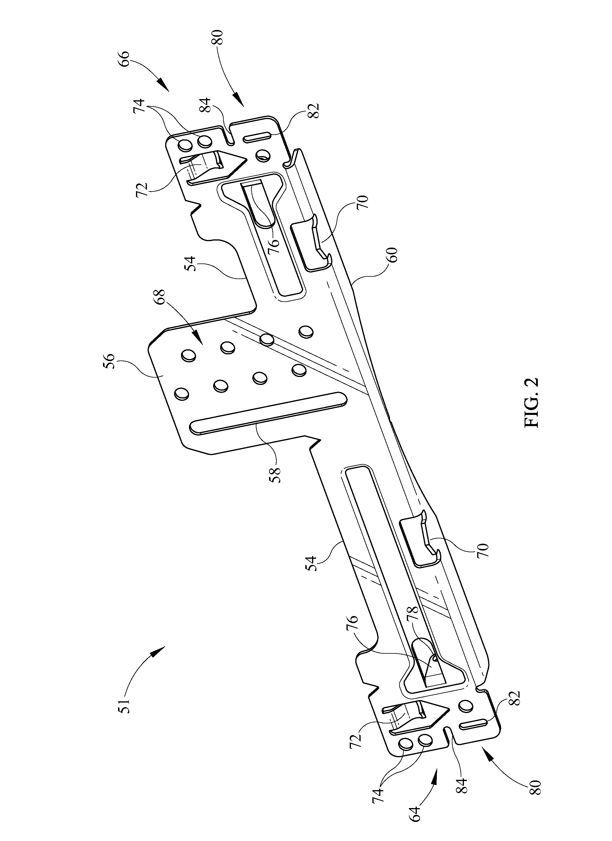
A T-bar mounting bracket assembly for a luminaire fixture frame having a bracket, a clip vertically adjustable relative to the bracket, the clip extending through an opening in the bracket, a fastener extending through the bracket and the clip and, the fastener spaced from a location where the clip passes through the opening.

Description

CROSS REFERENCES TO RELATED APPLICATIONS[0001]None.STATEMENT REGARDING FEDERALLY SPONSORED RESEARCH OR DEVELOPMENT[0002]None.REFERENCE TO SEQUENTIAL LISTING, ETC.[0003]None.BACKGROUND[0004]1. Field of the Invention[0005]The present invention relates to a luminaire mounting system. Specifically, the present invention relates to recessed luminaire fixture frame mounting system.[0006]2. Description of the Related Art[0007]In construction of buildings, it is known to install false or suspended ceilings beneath water pipes, heating ducts and electrical races in order to easily access such structures while concealing them from normal activity within a building or room. Typically, the false ceiling is formed of acoustical tiles or drywall tiles which are supported by a network of inverted T-shaped grid members. The T-grid members are supported from the building structure by a plurality of wires or stems and are typically formed of lightweight, small gauge sheet steel. Such construction min...

Claims


Application Information

Patent Timeline
Patent Type & Authority Applications(United States)
IPC IPC(8): F21V21/30F21V19/02
CPCF21V21/048
Inventor JONES, MARK O.RIPPEL, GRAHAM M.O'BOYLE, MICHAEL S.NEVERS, CRAIG S.
Owner SIGNIFY NORTH AMERICA CORP
Learn More