Pump body

Active Publication Date: 2011-04-07
LIBERTY OILFIELD SERVICES LLC
View PDF14 Cites 44 Cited by
  • Summary
  • Abstract
  • Description
  • Claims
  • Application Information

AI Technical Summary

Benefits of technology

[0015]The present application in one embodiment applies pre-compressive forces to raised surfac

Problems solved by technology

These stress cycles may induce fatigue failure of the fluid end.
However, the pl

Method used


Image

  • Pump body
  • Pump body
  • Pump body

Examples


Embodiment Construction

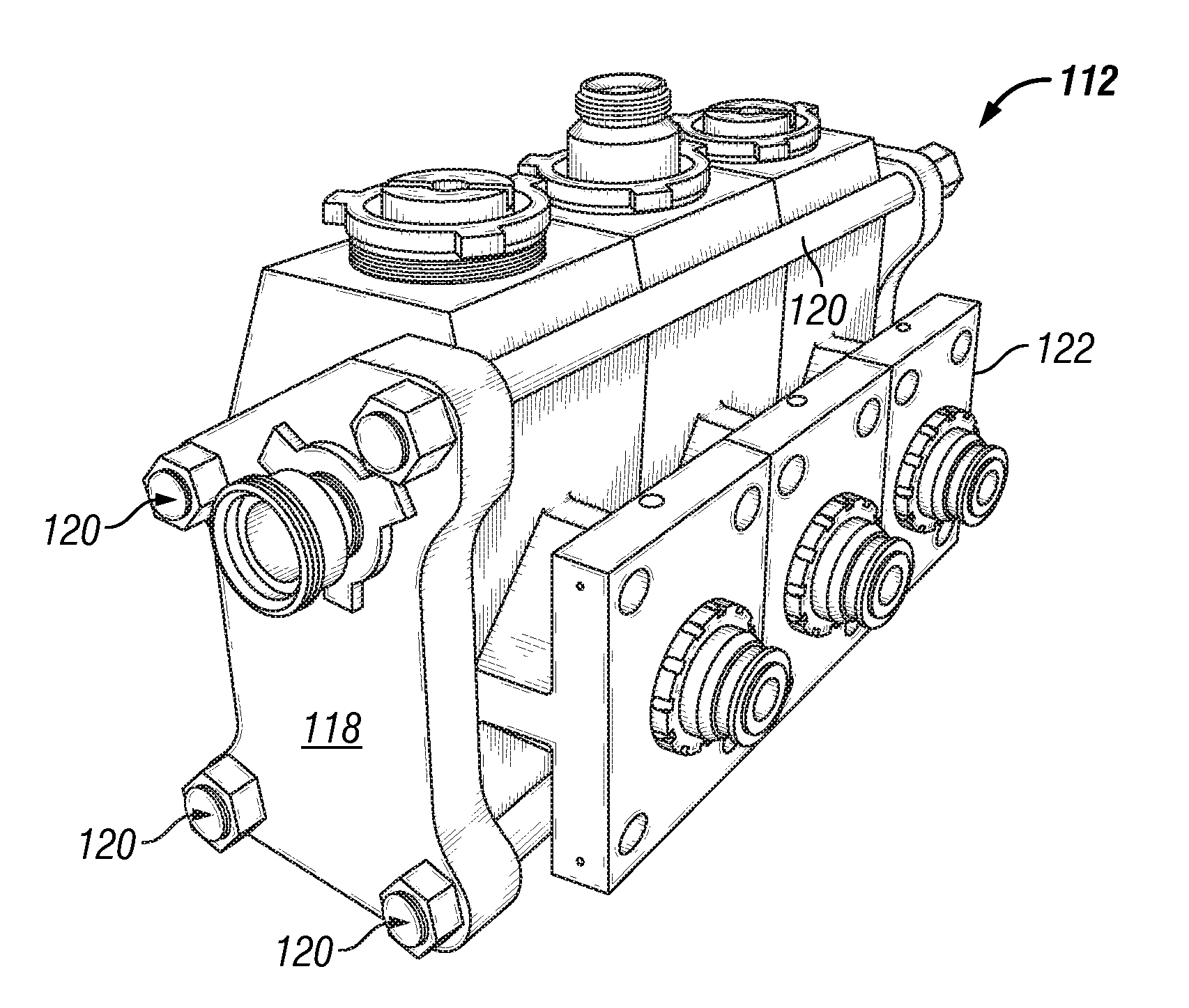
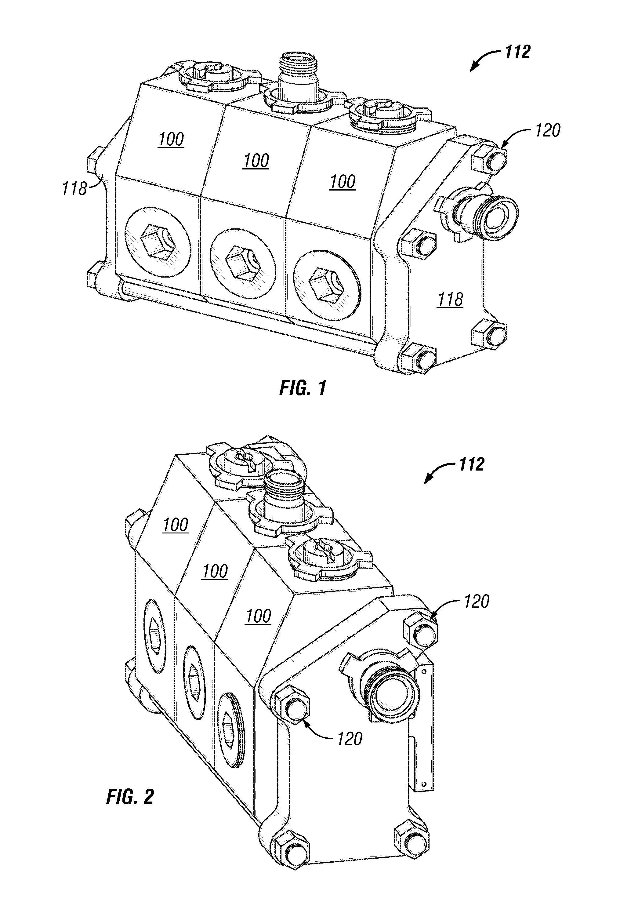
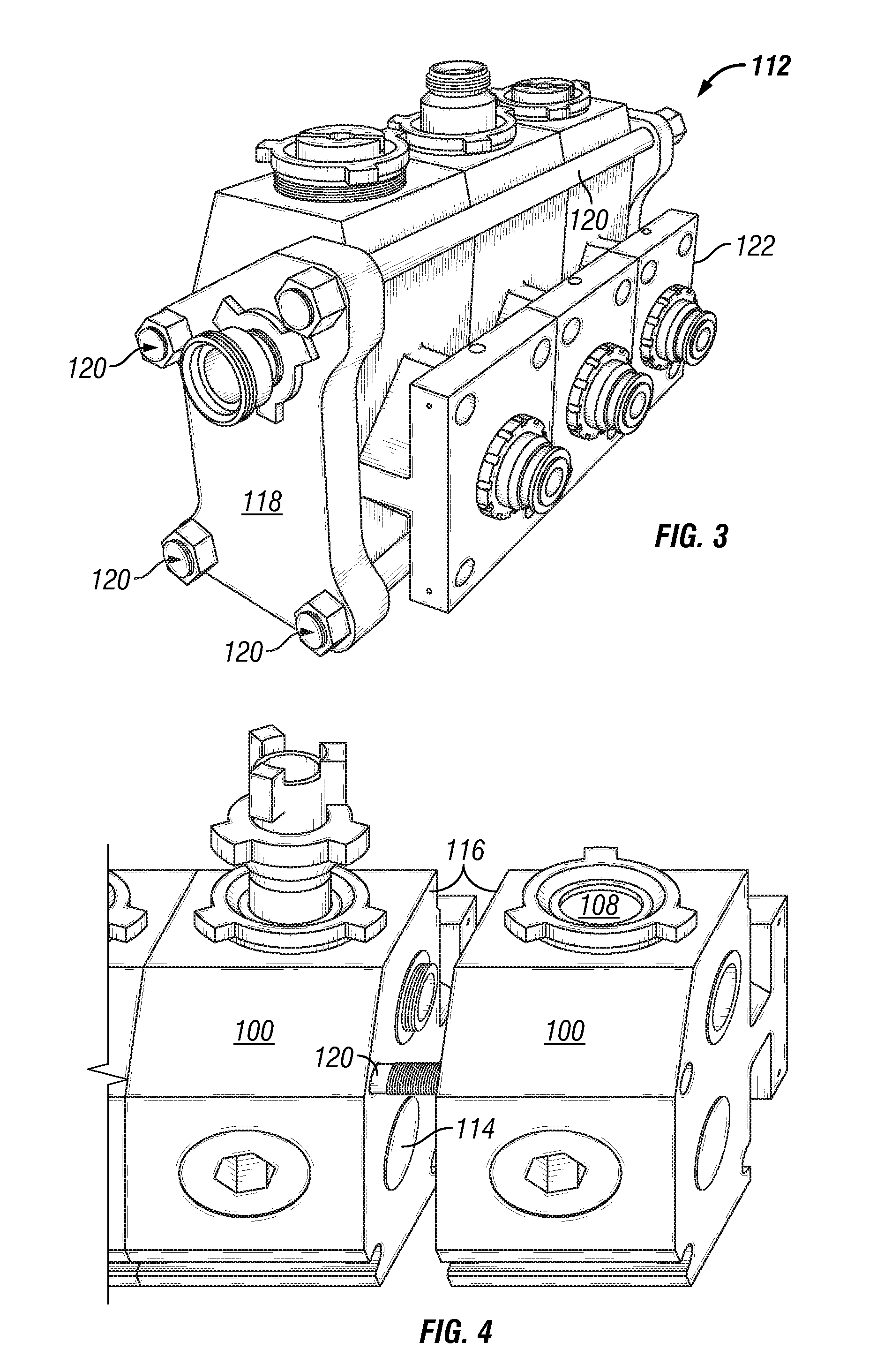
[0037]Referring now to all of the Figures, there is disclosed a pump body portion or fluid end, indicated generally at 100. The pump body portion 100 comprises a body 102 that defines an internal passage or piston bore 104 for a receiving a pump plunger (best seen in FIG. 7). The pump body portion 100 may further define an inlet port 106 and an outlet port 108. The inlet port 106 and the outlet port 108 may be substantially perpendicular to the piston bore 104, forming a conventional crossbore body portion 100, best seen in FIG. 6. The piston bore 104 may comprise a pair of bores, such as that shown in FIG. 9. The intersection of the piston bore 104 and the inlet and outlet ports 106 and 108 defines at least one area 110 of stress concentration that may be a concern for material fatigue failure. In addition to the stress concentration, the area 110 is subject to operational pressure of the pump discussed hereinabove, which may further increase its fatigue failure risk. Those skilled...


PUM

PropertyMeasurementUnit
Forceaaaaaaaaaa
Pressureaaaaaaaaaa
Stress optical coefficientaaaaaaaaaa

Abstract

A multiplex fluid pump assembled from a plurality of pump bodies connected side by side between opposing end plates with a plurality of fasteners tightened to compress the pump bodies between the end plates. Raised surfaces on opposite exterior side surfaces of each pump body are engaged with an adjacent end plate or an adjacent pump body to apply a pre-compressive force at the raised surfaces and thereby inhibit the initiation of fatigue cracks.

Description

CROSS REFERENCE TO RELATED APPLICATION(S)[0001]This application claims the benefit of and priority to provisional application U.S. 61 / 233,709, filed Aug. 13, 2009.STATEMENT REGARDING FEDERALLY SPONSORED RESEARCH OR DEVELOPMENT[0002]Not applicableTHE NAMES OF PARTIES TO A JOINT RESEARCH AGREEMENT[0003]Not applicableINCORPORATION BY REFERENCE OF MATERIAL SUBMITTED ON A COMPACT DISC[0004]Not applicableBACKGROUND OF THE INVENTION[0005](1) Field of the Invention[0006]The current application is related in general to wellsite surface equipment such as fracturing pumps and the like.[0007](2) Description of Related Art including information disclosed under 37 CFR 1.97 and 1.98[0008]Reciprocating pumps such as triplex pumps and quintuplex pumps are generally used to pump high pressure fracturing fluids downhole. Typically, the pumps that are used for this purpose have plunger sizes varying from about 7 cm (2.75 in.) to about 16.5 cm (6.5 in.) in diameter and may operate at pressures up to 144...

Claims


Application Information

Patent Timeline
IPC IPC(8): F04B41/06B23P15/00
CPCF04B53/14F04B53/12Y10T29/49236Y10T29/49252
Inventor OCHOA, BRIANGAMBIER, PHILIPPEFAUGERE, AUDESHEN, CHRISTOPHERHUBENSCHMIDT, JOECHUA, TZE WEITAYLOR, WALTER
Owner LIBERTY OILFIELD SERVICES LLC
Why Eureka
Try Eureka