Supercharge Your Innovation With Domain-Expert AI Agents!

Insulated mold cavity assembly and method for golf ball manufacturing

a golf ball and cavity mold technology, applied in cocoa, other domestic products, applications, etc., can solve the problems of low flow of materials, high cost of injection mold rim systems, and difficulty in casting and reaction injection molds (rims), and achieve the effect of reducing heat loss

Inactive Publication Date: 2011-04-07
JUST ADD TECH SOLUTIONS
View PDF9 Cites 10 Cited by
  • Summary
  • Abstract
  • Description
  • Claims
  • Application Information

AI Technical Summary

Benefits of technology

"The patent describes an injection molding assembly for molding thin layers or low-flow materials on golf balls. The assembly includes a cavity for molding the outer surface of the golf ball layer, a metal surface layer surrounding the cavity, and an insulating layer at least partially surrounding the metal surface layer. The insulating layer is made thicker to reduce heat loss through the metal layer. The assembly can also include different mold halves for forming a cavity for the outer cover or a multi-layer ball with different thickness regions. The technical effect of the invention is to improve the production of thin layers or low-flow materials on golf balls, which can enhance their performance and durability."

Problems solved by technology

Casting and Reaction Injection Mold (RIM) systems are expensive and very difficult to operate compared to an injection molding system.
However, without the technology to mold thin polyurethane covers, golf ball companies must resort to casting or RIM processes if they want to put a thin polyurethane cover on a golf ball.
It is difficult to injection mold very thin covers on golf balls using materials such as thermoplastics or thermoplastic elastomers because a point is reached where the heat removal from the injected material by the metal mold is such that the melted material can not fill the mold before “material freezing off” occurs.
Even with relatively thick covers, the use of a very low flow material can also have problems with “material freezing off” before the mold can be completely filled.

Method used


Image

  • Insulated mold cavity assembly and method for golf ball manufacturing
  • Insulated mold cavity assembly and method for golf ball manufacturing
  • Insulated mold cavity assembly and method for golf ball manufacturing

Examples


Embodiment Construction

.”

BRIEF DESCRIPTION OF THE DRAWINGS

[0014]Features, aspects, and embodiments are described in conjunction with the attached drawings, in which:

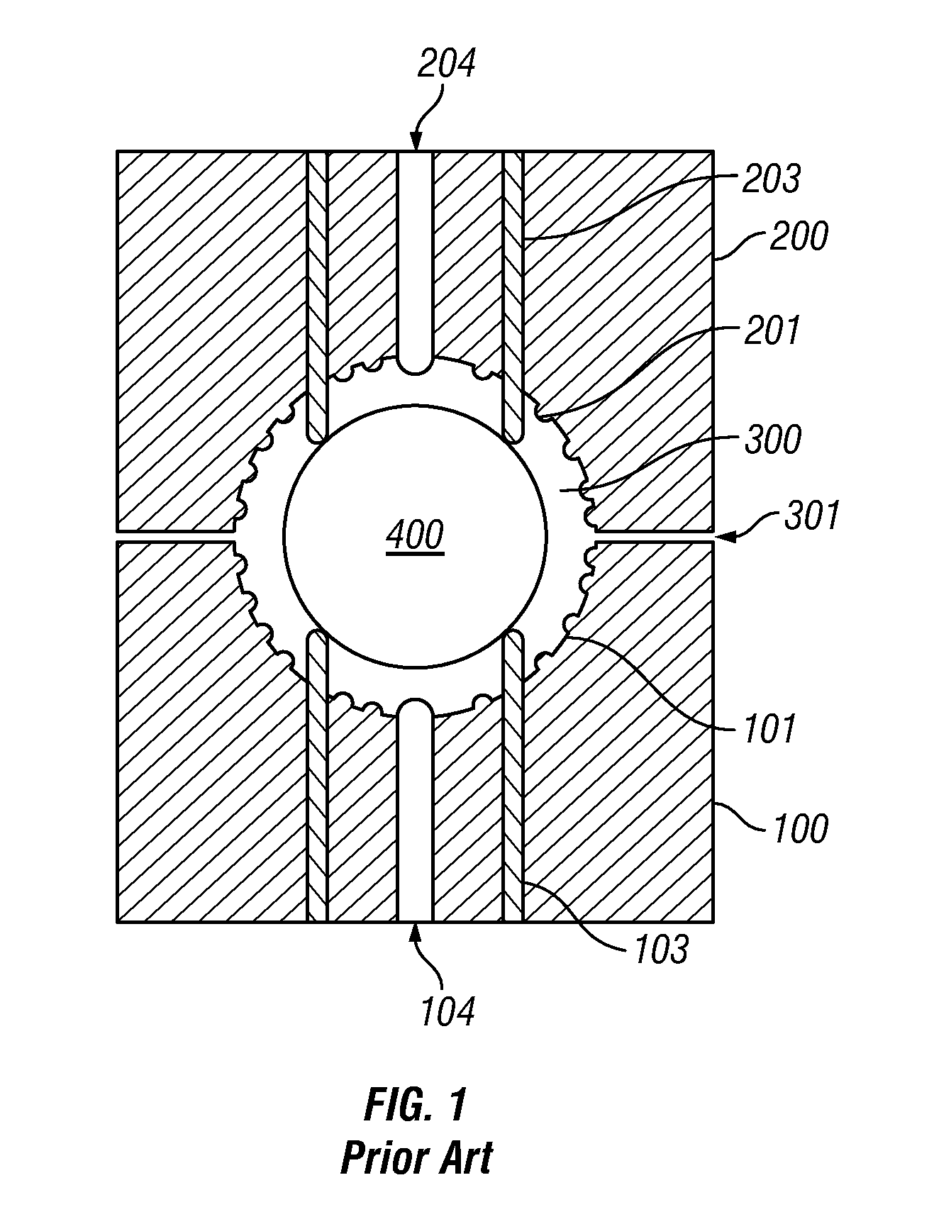
[0015]FIG. 1 is a cross-sectional diagram illustrating a conventional golf ball injection mold cavity assembly;

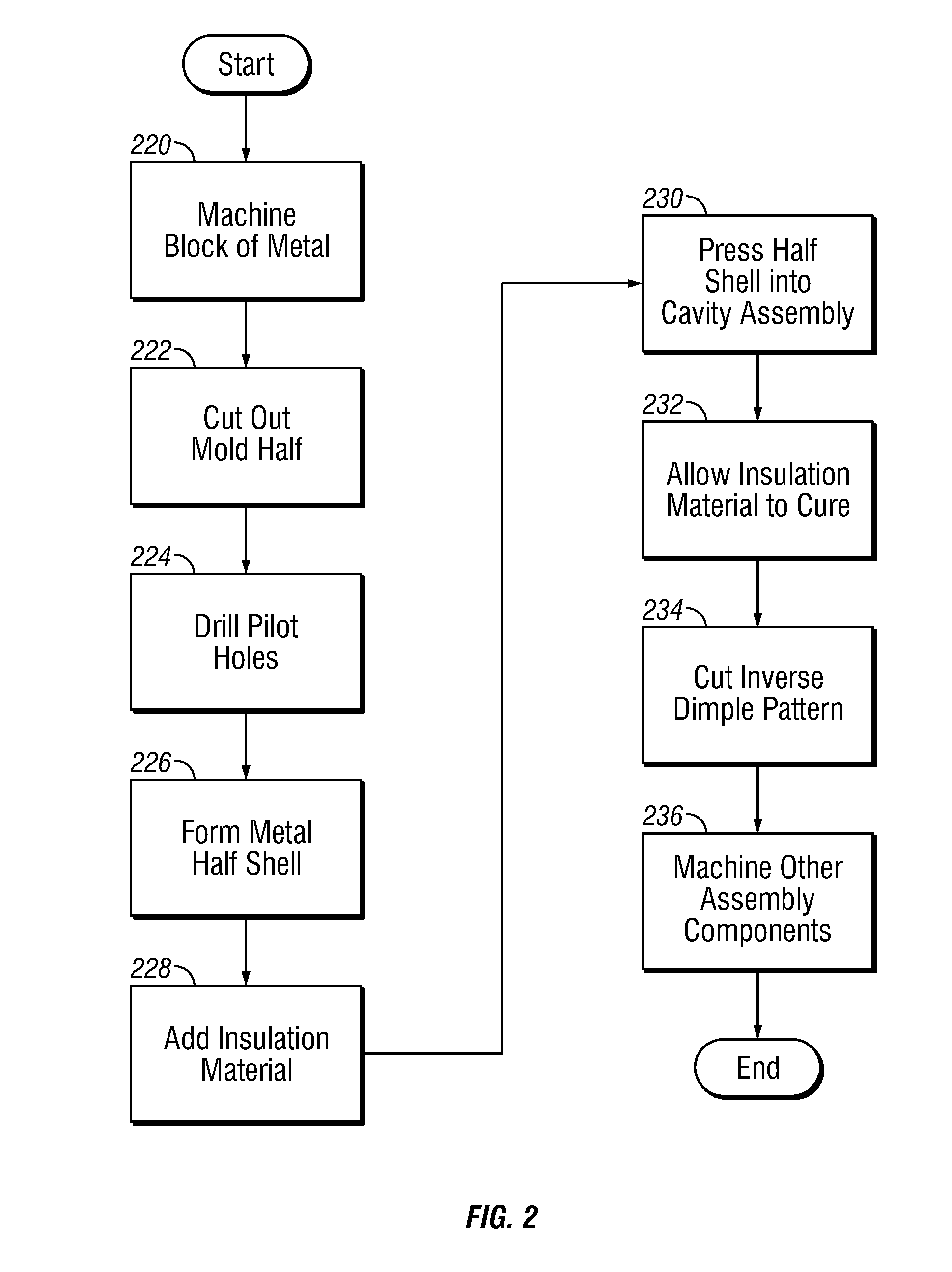
[0016]FIG. 2 is a flow chart illustrating an example method for constructing a golf ball injection mold cavity in accordance with one embodiment; and

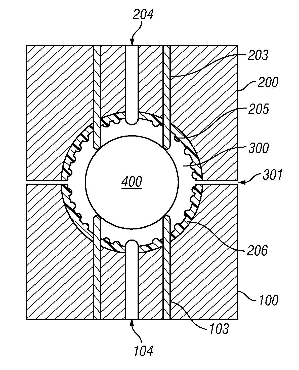
[0017]FIGS. 3-9 are cross-sectional diagrams illustrating examples of golf ball injection mold cavity assemblies configured in accordance with various embodiments;

[0018]FIG. 10 is a side perspective view of the metal molding surface or half shell used in one mold half of another embodiment of an insulated injection mold cavity assembly;

[0019]FIG. 11 is a bottom perspective view illustrating the lower surface of the metal molding layer illustrated in FIG. 10;

[0020]FIG. 12 is a vertical cross-sectional view through a metal part used in forming the metal molding layer or half shell of FIGS. ...


PUM

PropertyMeasurementUnit
thicknessaaaaaaaaaa
thicknessaaaaaaaaaa
thicknessaaaaaaaaaa

Abstract

An insulated injection molding cavity assembly for molding a thin or low flow material golf ball cover or mantle layer, comprises a cavity for defining a golf ball layer, the golf ball layer comprising a thickness that corresponds to a space defined by the cavity; a metal surface layer surrounding the cavity, and an insulating layer surrounding the metal surface layer. The metal surface layer thickness is decreased and the insulating layer thickness is increased with decreasing golf ball layer thickness.

Description

RELATED APPLICATIONS INFORMATION[0001]This application claims priority under 35 U.S.C. §119(e) to U.S. Provisional Patent Application Ser. No. 61 / 248,828, filed Oct. 5, 2009, and entitled “Insulated Cavity,” which is incorporated herein by reference in its entirety as if set forth in full.BACKGROUND[0002]1. Technical Field[0003]The embodiments described herein relate generally to the manufacture of golf balls, and specifically to a cavity mold assembly for injection molding a golf ball cover on a golf ball, using a layer of insulating material between the metal cavity mold halves and the injection molded material to slow the freezing of the injected material and thus enable a thin cover or a low-flow material cover to be molded before “material freeze-off” occurs.[0004]2. Related Art[0005]Some of the most popular balls in the golf industry have polyurethane covers that are less than 0.035″ thick, which is too thin to injection mold easily using standard injection molding cavities. A...

Claims


Application Information

Patent Timeline
Patent Type & Authority Applications(United States)
IPC IPC(8): B29C45/14B29C45/37
CPCB29C45/0025B29C45/14065B29C45/14819B29L2031/54Y10T29/49885B29C45/04B29K2905/00B29L2031/546B23P15/24B29C33/38B29C33/76B29C45/26
Inventor FELKER, DAVID L.
Owner JUST ADD TECH SOLUTIONS
Features
  • R&D
  • Intellectual Property
  • Life Sciences
  • Materials
  • Tech Scout
  • Unparalleled Data Quality
  • Higher Quality Content
  • 60% Fewer Hallucinations
Learn More