Training machine and method for controlling training machine

a training machine and training method technology, applied in the field of training devices, can solve the problems of reducing load, unable to obtain a full concentric exercise, and inability to apply appropriate load to an exerciser, and achieve the effect of safely and effectively exercising

Inactive Publication Date: 2011-04-07
HITACHI LTD +1
View PDF12 Cites 21 Cited by
  • Summary
  • Abstract
  • Description
  • Claims
  • Application Information

AI Technical Summary

Benefits of technology

According to the present invention, it can provide a training device and a control method of the training device to exercise safely and effectively under the load suitable for exercise capacity or physical function of each exerciser.

Problems solved by technology

However, a technology disclosed in Japanese patent unexamined laid-open publication No 204850 of 2001 is designed to change load applied to an exerciser by a relative exercise position of the press board at the time of leg press in the training device.
Accordingly, it has a problem, in which an appropriate load cannot be applied to an exerciser, when sitting place or posture of an exerciser deviate somewhat from a prescribed position.
Then, it has a problem to fail in obtaining a full concentric exercise applying load bidirectionally although load reduces according to a degree of fatigue of an exerciser.

Method used


Image

  • Training machine and method for controlling training machine
  • Training machine and method for controlling training machine
  • Training machine and method for controlling training machine

Examples


first embodiment

A First Embodiment

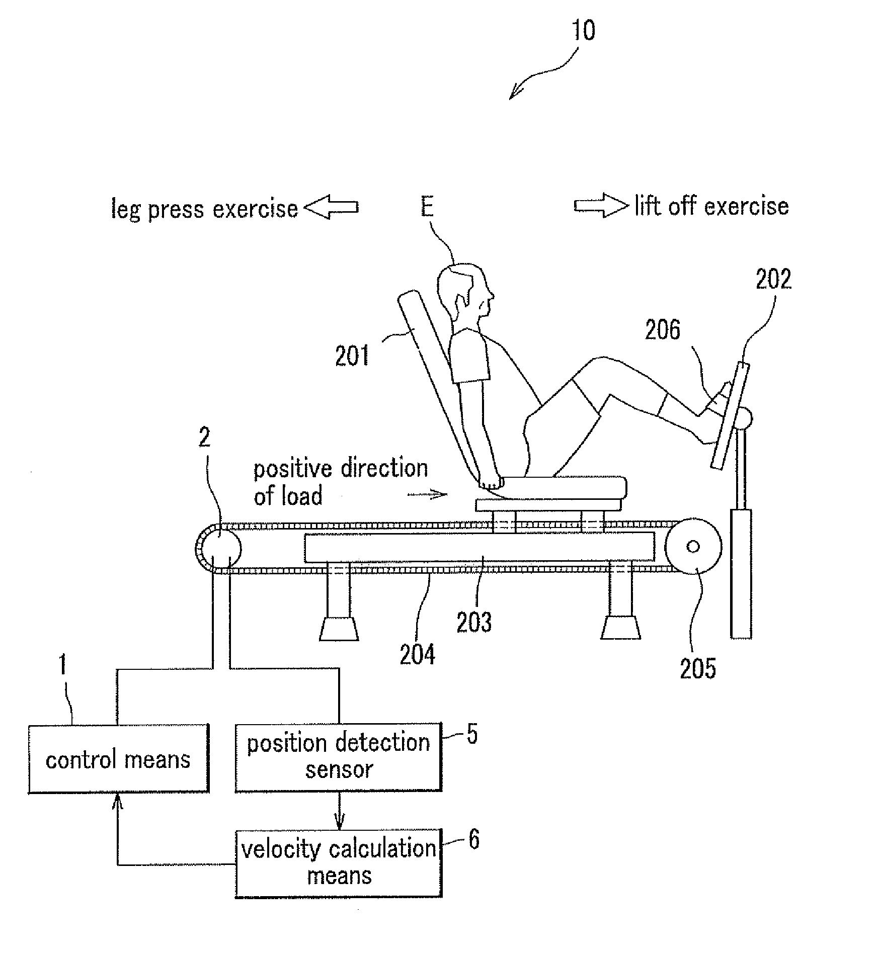
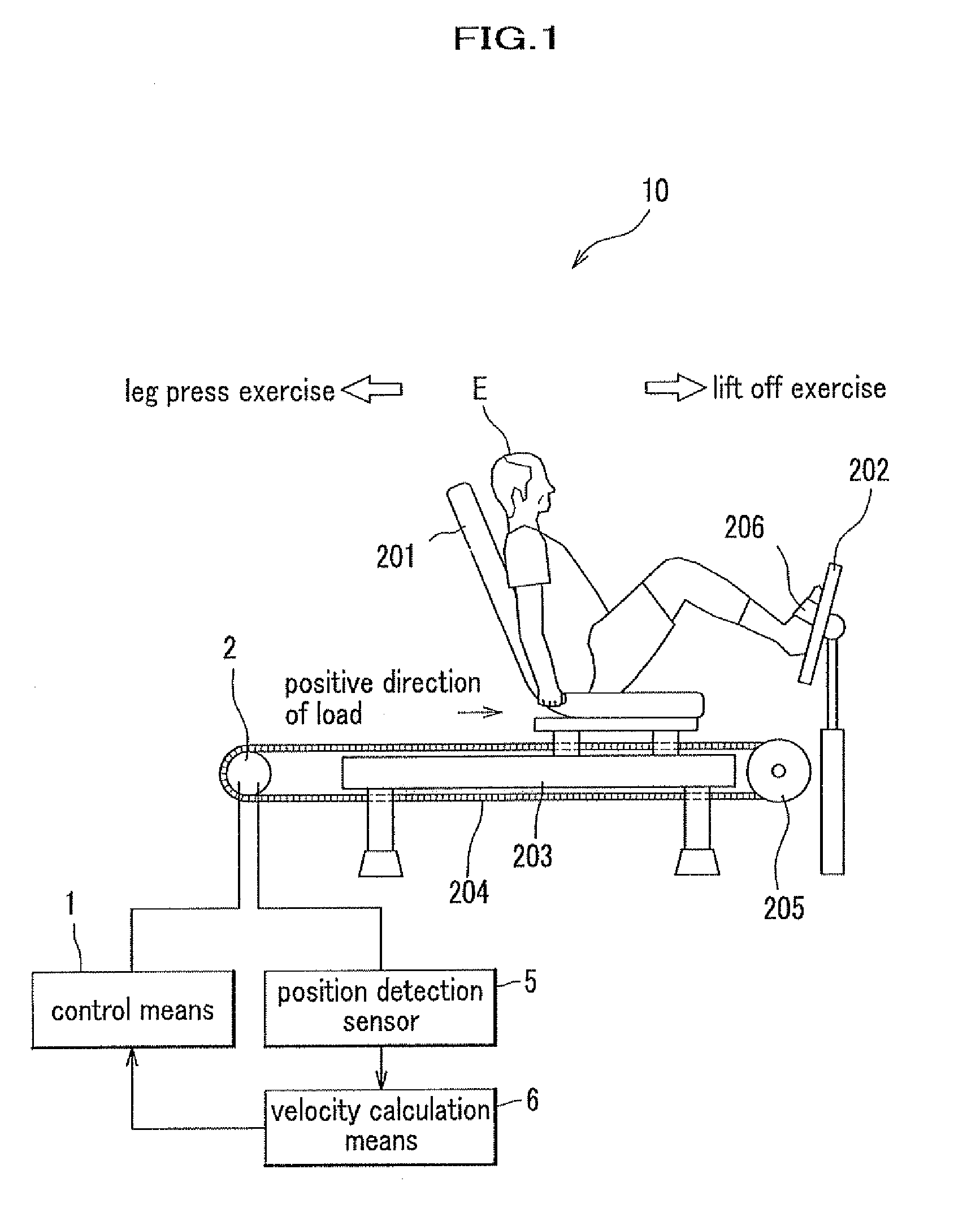
At first, a constitution of the training device will be described for readily understanding thereof. FIG. 1 is a constitution of the training device relating to each embodiment of the present invention. As shown in FIG. 1, the training device 10 includes a control means 1, a servomotor 2, a position detection sensor 5, a velocity calculation means 6, a chair 201, a press board 202, a rail 203, a belt 204, a pulley 205, and a fixed member 206.

The control means 1 is a means for generating driving current of the servomotor 2 in accordance with velocity data (rotary velocity of the servomotor 2 or linear moving velocity of the belt 204) received from the velocity calculation means 6. The servomotor 2 is designed to rotate by driving current generated by the control means 1, generate rotary torque corresponding to a magnitude of driving current, and give linear driving power transmitted through the belt 204.

The chair 201 is a means for sitting down during the training o...

second embodiment

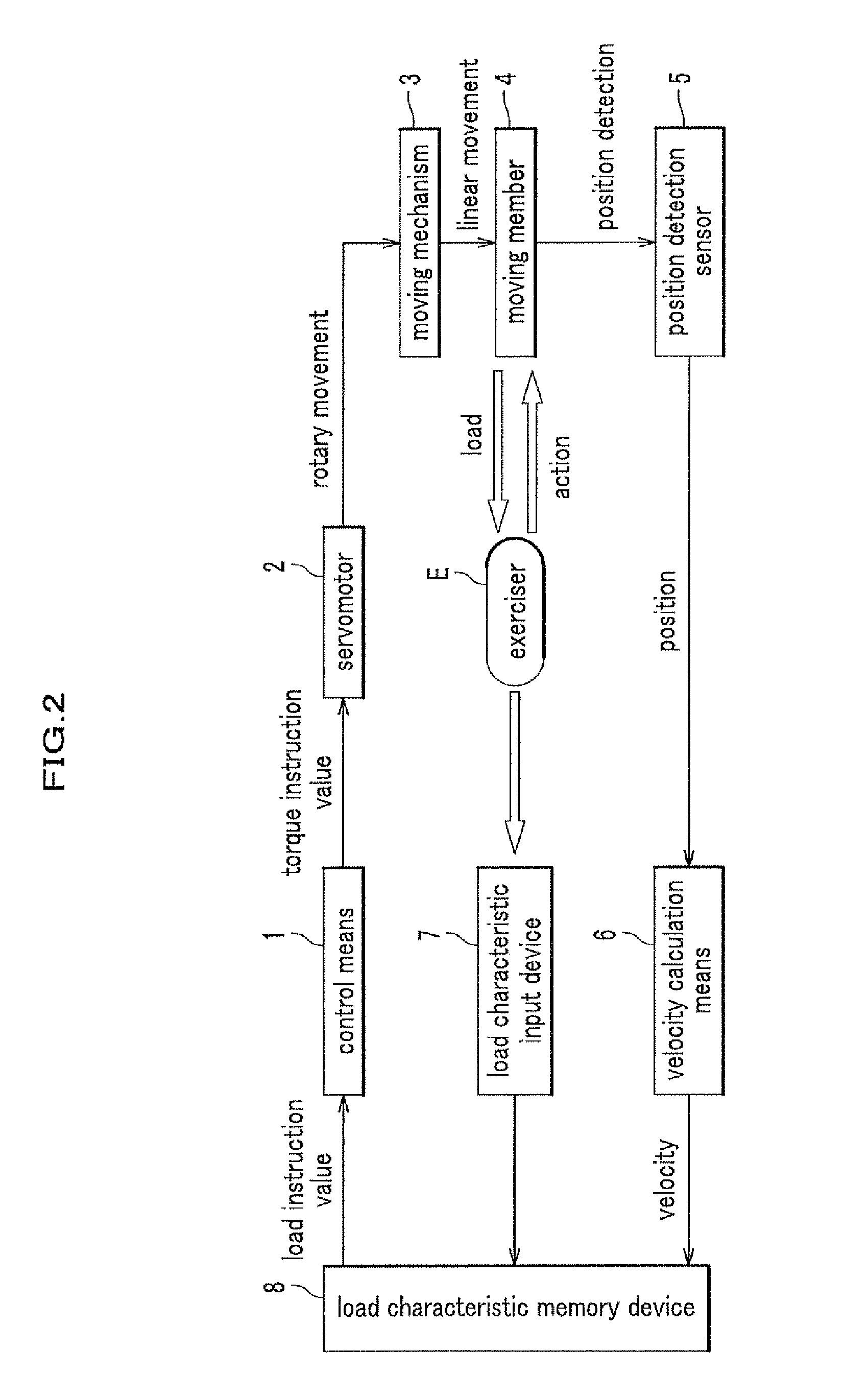
FIG. 4 is a view of system configuration of the training device relating to a second embodiment of the present invention. Different from the system configuration in FIG. 2, a system configuration in FIG. 4 has not the position detection sensor 5 and the velocity calculation means 6, but a control unit 9 for inputting each of set values. That is, a system of this training device is constituted to include the control means 1, the servomotor 2, the movement mechanism 3, the movable member 4, the load characteristic input device 7, the load characteristic memory device 8, and the control unit 9.

Although the system configuration of the training device in FIG. 2 is constituted to input the velocity-load characteristic in the load characteristic input device 7 by the exerciser E, the system configuration of the training device in FIG. 4 is constituted to input various kinds of set values in the control unit 9 according to a strength of self-consciousness of the exerciser E by a trainer (at...

third embodiment

FIG. 6 is a view of system configuration of the training device relating to a third embodiment of the present invention.

The system configuration in FIG. 6 is a combination of the system configuration of the first embodiment shown in FIG. 2 and the system configuration of the second embodiment shown in FIG. 4.

A system of this training device is constituted to include the control means 1, the servomotor 2, the movement mechanism 3, the movable member 4, the position detection sensor 5, the velocity calculation means 6, the load characteristic input device 7, the load characteristic memory device 8, and the control unit 9.

FIG. 7 is a view of the velocity-load characteristic inputted in the training device in FIG. 6, and its horizontal axis represents a velocity and the vertical axis represents a load. This velocity-load characteristic shows the load characteristic depending on the velocity changing in a magnitude of load according to the velocity within an area (within an area between ...


PUM


Abstract

A training machine for enabling the exerciser to exercise under a load appropriate for the individual exercise capability and physical function of the exerciser. The exerciser (E) enters a desired velocity-load characteristic into a load characteristic input device (7), and the velocity-load characteristic is stored in the load characteristic memory device (8). A load instruction value is determined according to the velocity-load characteristic and to the velocity inputted from a velocity calculation means (6) into the load characteristic memory device (8) and transmitted to a control means (1). The control means (1) rotates a servomotor (2) with a torque instruction value corresponding to the load instruction value. A movement mechanism (3) converts the rotation into linear movement to move a movable unit (4). With this, the exerciser can carry out training of reciprocal movement.

Description

TECHNICAL FIELDThe present invention relates to a training device etc. for a muscular workout of an exerciser. In particular, it relates to the training device and a control method of the training device for applying load to the exerciser by a rotary torque of an electric motor.BACKGROUND ARTIn recent years, exercisers are increasing in number with use of the training device in a fitness gym or the like along with a health-oriented surge. As a governmental policy, from a viewpoint for preventing care of aged person in order not to be a man requiring caretakers or the like, aged person are increasing in number doing the muscular workout for the sake of maintenance in healthy condition or prevention of reduction in physical strength. As such a training device, there are, for example, a leg press machine for strengthening leg muscles or a chest press machine for strengthening chest and arm muscles. As a training device for such a use, a plate weight method applying load to an exerciser...

Claims


Application Information

Patent Timeline
Patent Type & Authority Applications(United States)
IPC IPC(8): A63B21/00
CPCA63B21/00069A63B21/002A63B21/0058A63B23/03525A63B23/0405A63B21/1488A63B2021/0026A63B2208/0238A63B2220/13A63B2220/30A63B2220/40A63B24/0087A63B21/4045
Inventor ISHII, HIROSHIOHNO, KOUICHIYAEGASHI, HIROSHIYUGE, KAZUOKATOU, MASAHIROIWAMOTO, YUKIHIDEHASHIZUME, MAKOTOKENMOTSU, HAJIMETAKASUGI, SHINICHIRO
Owner HITACHI LTD
Why Eureka
Try Eureka