
Method and apparatus for bone graft insertion

Inactive Publication Date: 2011-04-07
BAXANO SURGICAL
View PDF22 Cites 23 Cited by
  • Summary
  • Abstract
  • Description
  • Claims
  • Application Information

AI Technical Summary

Benefits of technology

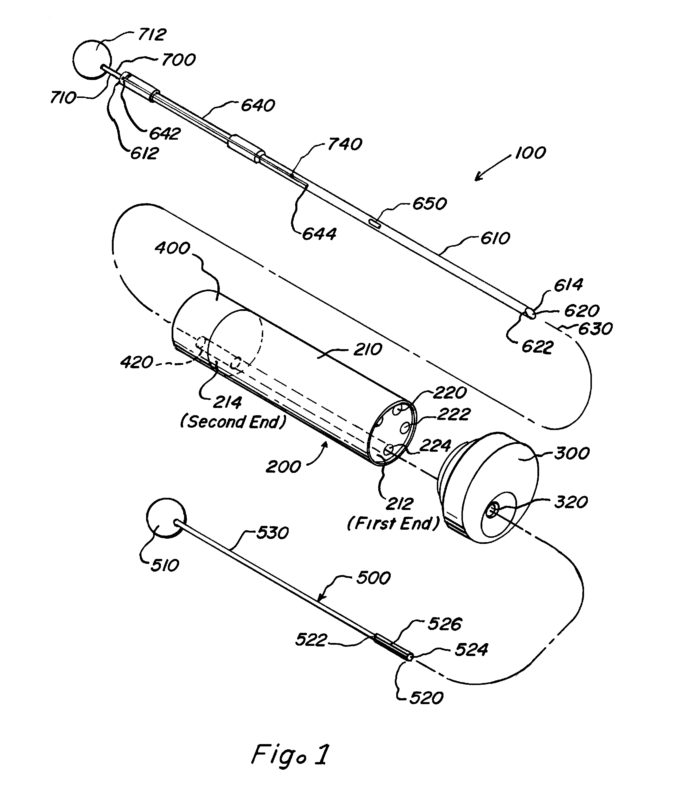
[0011]An improved materials delivery system includes a pre-loading assembly and a dispenser or inserter assembly for introducing material along an access path to a treatment site. The inserter assembly is adapted to be introduced percutaneously through tissue to an access point on the spine in a minimally invasive, low trauma manner, to provide therapy to the spine following nucleectomy. The system and assemblies are designed to accommodate the methods of loading and deploying of a wide variety of bone graft materials substantially without the concomitant introduction of air, vapor or other gases, such as compressed air, while governing the volume and rate of said bone graft material delivery.

Problems solved by technology

Autografts are used, but the amount of available autograft is limited in terms of locally recoverable volume, and by morbidity concerns related to autograft harvesting from a patient's other anatomical areas (e.g., iliac crest; other vascularized or non-vascularized autogenous cortical, cancellous, or corticocancellous bone; aspirated and / or enriched bone marrow stromal cells).
Allograft (e.g., mineralized or de-mineralized; donor or cadaver) can “extend” autograft, but limitations include risk of disease transmission, or limitations with respect to biological properties and mechanical properties.
However, it has also been observed that complications can occur during the insertion of bone graft materials when some bone graft insertion tools are used.
That is, if too great a volume of bone graft material is delivered in situ too quickly and with too much accompanying air and pressure (in part, an inherent result of bone graft material inserter design), adverse events may occur.

Method used


Image

  • Method and apparatus for bone graft insertion
  • Method and apparatus for bone graft insertion
  • Method and apparatus for bone graft insertion

Examples


Embodiment Construction

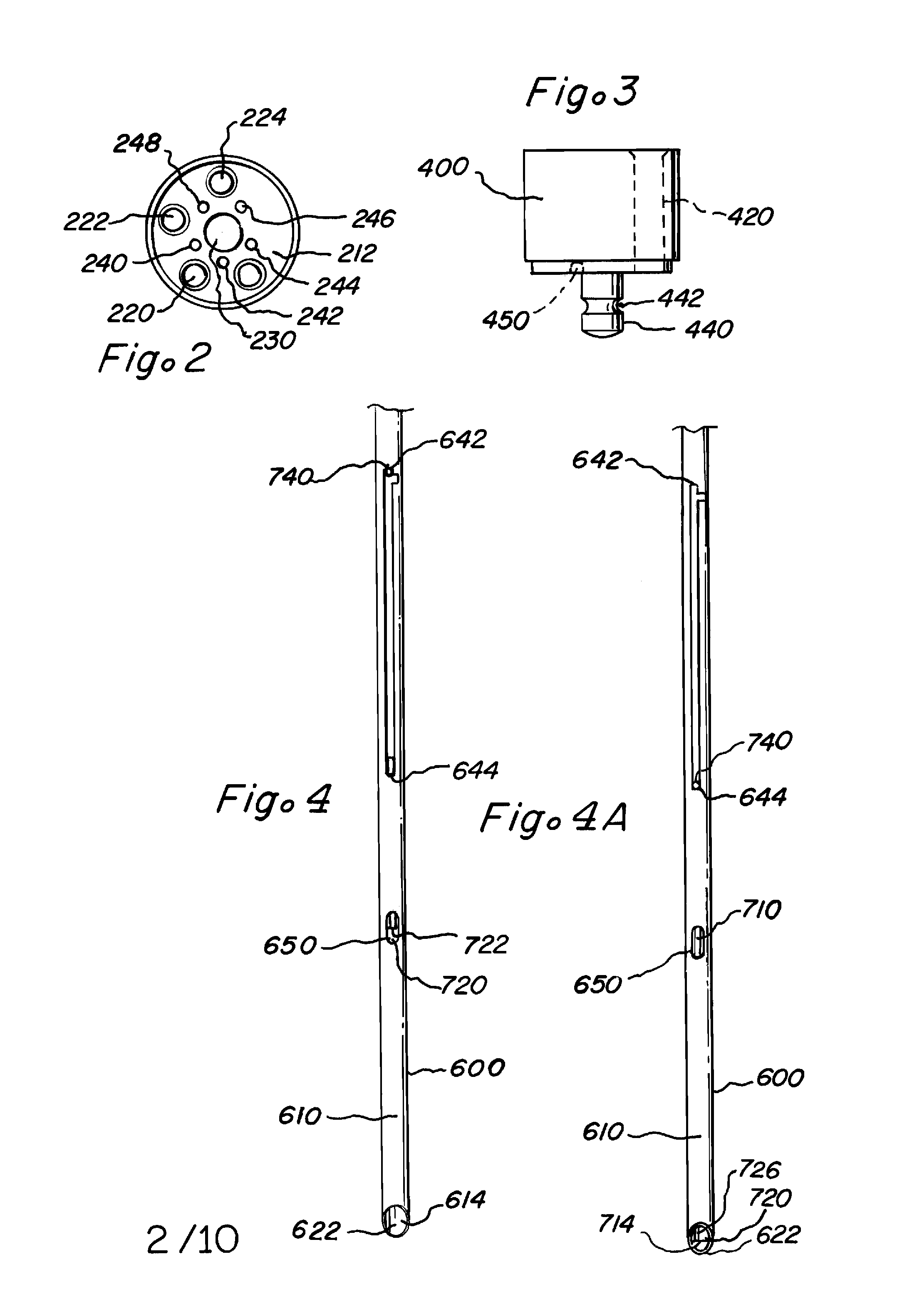
[0041]The present disclosure provides apparatus and methods for use in the introduction of bone graft materials. The figures generally illustrate examples of apparatus including aspects of the present disclosure. The particular exemplary embodiments of the apparatus and methods illustrated in the figures have been chosen for ease of explanation and understanding of various aspects of the present disclosure. These illustrated examples are not meant to limit the scope of coverage but instead to assist in understanding the context of the language used in this specification and the appended claims. Accordingly, variations of the disclosed and methods for use in the introduction of bone graft materials different from the illustrated examples may be encompassed by the appended claims.

[0042]The examples described in detail below are used to introduce or dispense bone graft material as part of spinal fusion procedure, also known as an arthrodesis. There are many steps and variations of spin...


PUM


Abstract

An apparatus for loading a bone graft material includes a preloading assembly, and a dispenser assembly. A method of dispensing bone graft material includes loading bone graft material into the preloader, compacting the material and transferring the compacted bone graft material into the cannula. The compacted bone graft material is vented to release unwanted or undesirable air, vapor or other gases from the bone graft material. The bone graft material is dispensed after the cannula is placed in a desired or selected position with respect to an intervertebral space.

Description

CROSS REFERENCE TO RELATED APPLICATIONS[0001]The present application claims benefit and priority to U.S. Prov. Pat. Appl. No. 61 / 195,022 entitled BONE GRAFT INSERTION SYSTEM, filed on Oct. 2, 2008 which is hereby incorporated by reference into the present disclosure. A Patent Cooperation Treaty application assigned Ser. No. PCT / US2009 / ______, entitled METHOD AND APPARATUS FOR BONE GRAFT INSERTION, filed on Oct. 2, 2009, and having identical inventorship is also hereby is incorporated by reference into the present disclosure in its entirety.BACKGROUND[0002]1. Field[0003]The present disclosure relates generally to medical procedures and in particular, minimally invasive medical procedures. One application of the present teachings is in providing therapy to adjacent spinal vertebrae. More specifically, one application uses instrumentation systems that facilitate the safe and effective deployment and placement of augmentation media, such as bone growth materials or bone graft materials,...

Claims


Application Information

Patent Timeline
IPC IPC(8): A61M5/36A61M5/00
CPCA61B17/8827A61B17/8819
Inventor BARNHOUSE, MICHAEL P.FEILER, JR., FREDERIC CHARLESHILL, WALTER SCOTT
Owner BAXANO SURGICAL
Learn More