Hydraulic Internal Combustion Engines

Active Publication Date: 2011-04-14
STURMAN DIGITAL SYST
View PDF112 Cites 39 Cited by
  • Summary
  • Abstract
  • Description
  • Claims
  • Application Information

AI Technical Summary

Problems solved by technology

However, the use of the piston and crankshaft mechanism introduces many constraints in the operation of the

Method used


Image

  • Hydraulic Internal Combustion Engines
  • Hydraulic Internal Combustion Engines
  • Hydraulic Internal Combustion Engines

Examples


Embodiment Construction

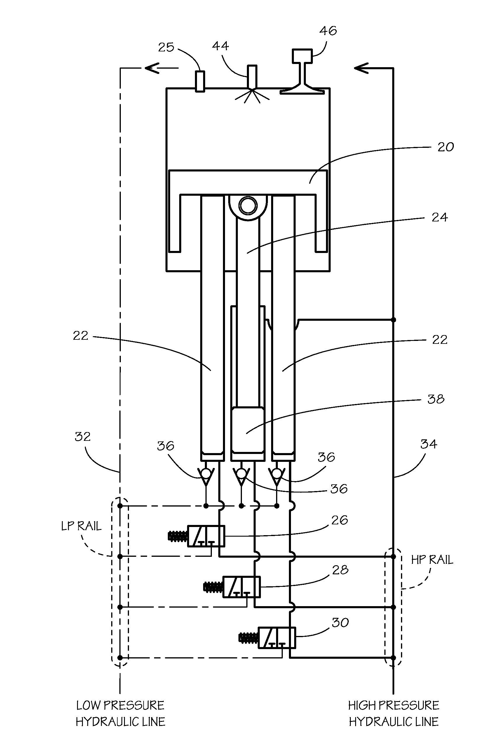
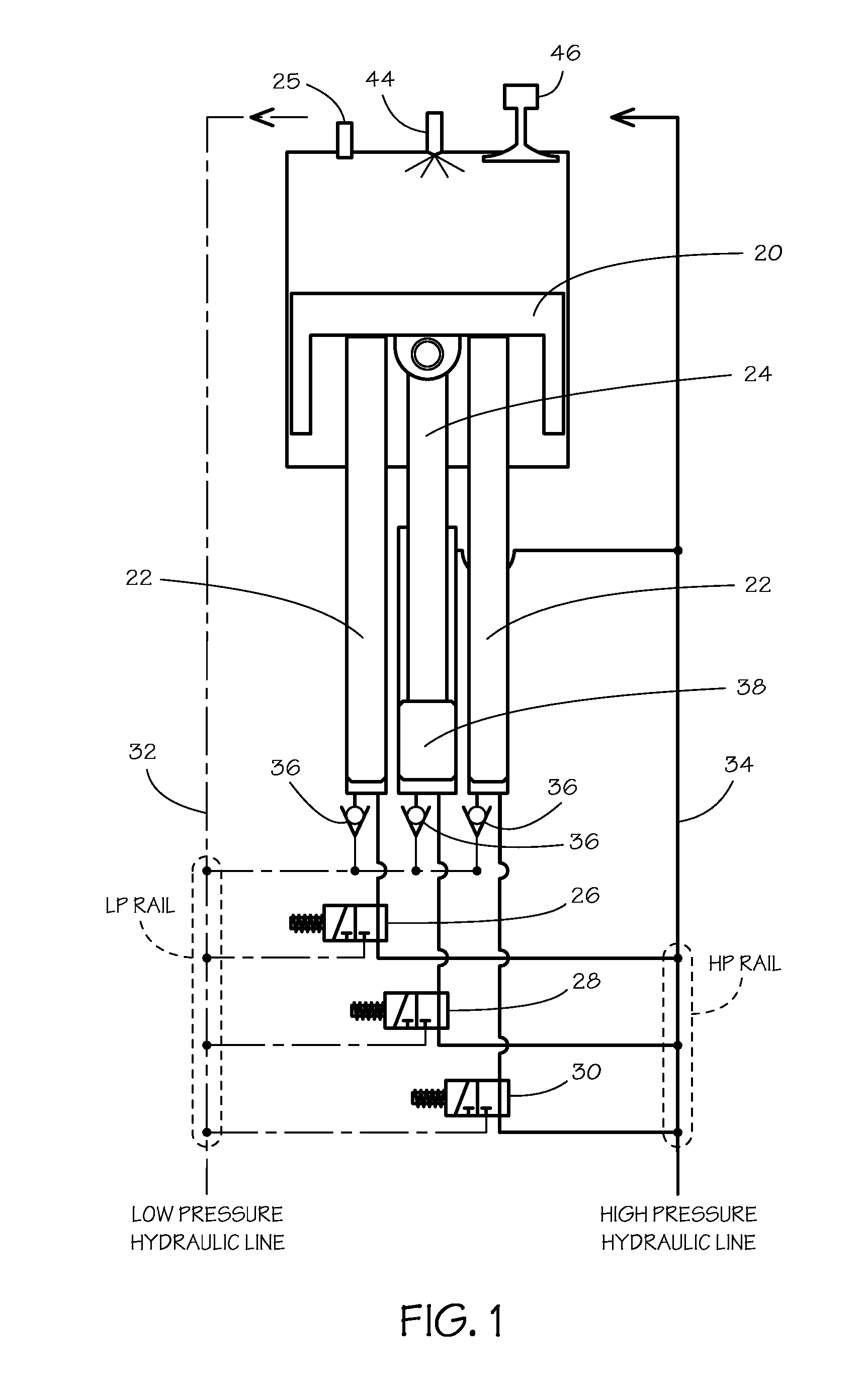
[0026]Disclosed herein is a free-piston type hydraulic internal combustion engine with fully variable electronically controlled hydraulic valve actuation, high pressure electronically controlled fuel injection, and a power train useable therewith. In the description to follow, disclosure of certain aspects of the invention with respect to one embodiment in general includes the possibility of use of those aspects in other embodiments as well.

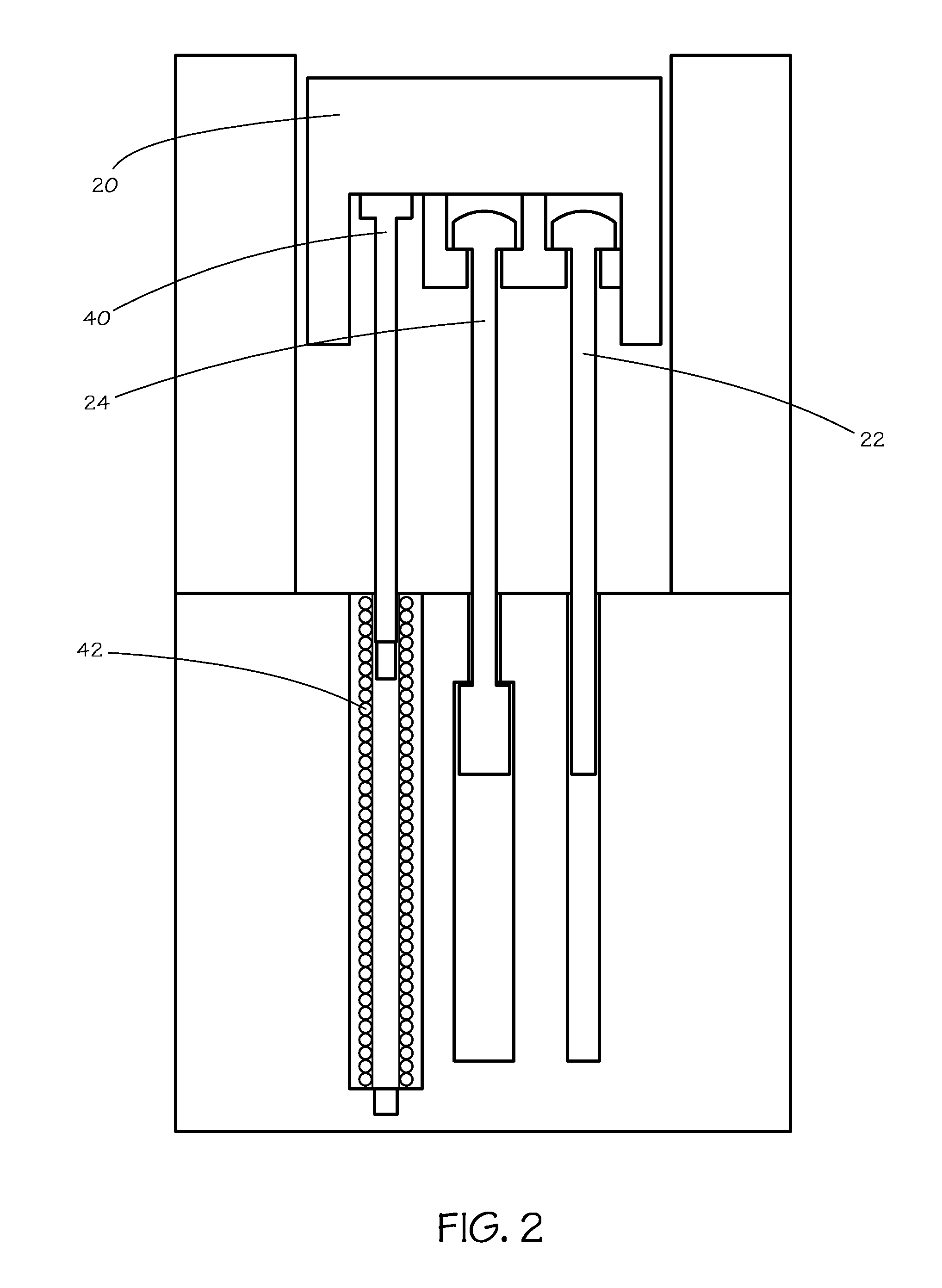
[0027]One cylinder of an engine in accordance with the present invention is schematically shown in FIG. 1. The two main subassemblies in the engine include the cylinder head assembly and the piston / plunger assembly with hydraulic valves. They are relatively independent of each other and will be described separately.

[0028]In this embodiment, the cylinder head assembly incorporates high pressure electronically controlled fuel injectors 44 using intensifier type fuel injectors, and a Hydraulic Valve Actuation system 46 of the general type disclosed ...


PUM


Abstract

Hydraulic internal combustion engines having at least one combustion piston not mechanically connected to a crankshaft or any other combustion piston, but instead acting on hydraulic plungers through valving that is electronically controlled to control the piston position and velocity, typically through an intake stroke, a compression stroke, a combustion or power stroke and an exhaust stroke. Electronically controlled fuel injection and electronically controlled engine valves provided great flexibility in the operating cycles that may be used, with the engine pumping hydraulic fluid to a high pressure accumulator for use in hydraulic motors or other hydraulic equipment. Embodiments using high pressure air injection to sustain combustion are also disclosed.

Description

CROSS-REFERENCE TO RELATED APPLICATIONS[0001]This application claims the benefit of U.S. Provisional Patent Application No. 61 / 250,784 filed Oct. 12, 2009, U.S. Provisional Patent Application No. 61 / 298,479 filed Jan. 26, 2010, U.S. Provisional Patent Application No. 61 / 300,403 filed Feb. 1, 2010 and U.S. Provisional Patent Application No. 61 / 320,943 filed Apr. 5, 2010.BACKGROUND OF THE INVENTION[0002]1. Field of the Invention[0003]The present invention relates to the field of free piston engines and power trains therefore.[0004]2. Prior Art[0005]Internal combustion engines are useful devices for converting chemical energy to mechanical energy by combustion. Typical internal combustion engines convert the energy in petrochemical fuels such as gasoline or diesel fuel to rotary mechanical energy by using the pressure created by confined combustion to force a piston downward as the combustion gases expand and to convert that motion into a rotary motion by use of a crankshaft. However, ...

Claims


Application Information

Patent Timeline
IPC IPC(8): F02B71/04
CPCF02B71/045F01B11/006
Inventor STURMAN, ODED EDDIEKISS, TIBORMASSEY, STEVEN E.DRURY, DAVID
Owner STURMAN DIGITAL SYST
Why Eureka
Try Eureka