Grill handle with heat shield

a grill handle and heat shield technology, applied in the field of grill handle, can solve the problems of less functional and wear resistance, less aesthetics, and difficulty in compact packaging of the grill for retail sale, and achieve the effect of increasing the distance between the handle and the cooking chamber, and high temperature threshold

Active Publication Date: 2011-04-14
WEBER-STEPHEN PRODUCTS
View PDF20 Cites 21 Cited by
  • Summary
  • Abstract
  • Description
  • Claims
  • Application Information

AI Technical Summary

Benefits of technology

[0011]Several embodiments of barbecue grill with a heat barrier or shield for a barbecue grill handle are described and claimed herein. These embodiments employ various solutions for reducing the temperature of, and in the region of, a barbecue grill handle that run contrary to the accepted solutions of other individuals possessing skill in the per

Problems solved by technology

Although the two solutions identified above are sufficient to meet the EN 1860-1:2003 standard, they both have their drawbacks.
For example, both solutions result in an appearance which is less aesthetically pleasing and possibly less functional and wear-resistant.
Increasing the distance between the handle and the grill can give a barbecue grill a less proportional ap

Method used


Image

  • Grill handle with heat shield
  • Grill handle with heat shield
  • Grill handle with heat shield

Examples


first embodiment

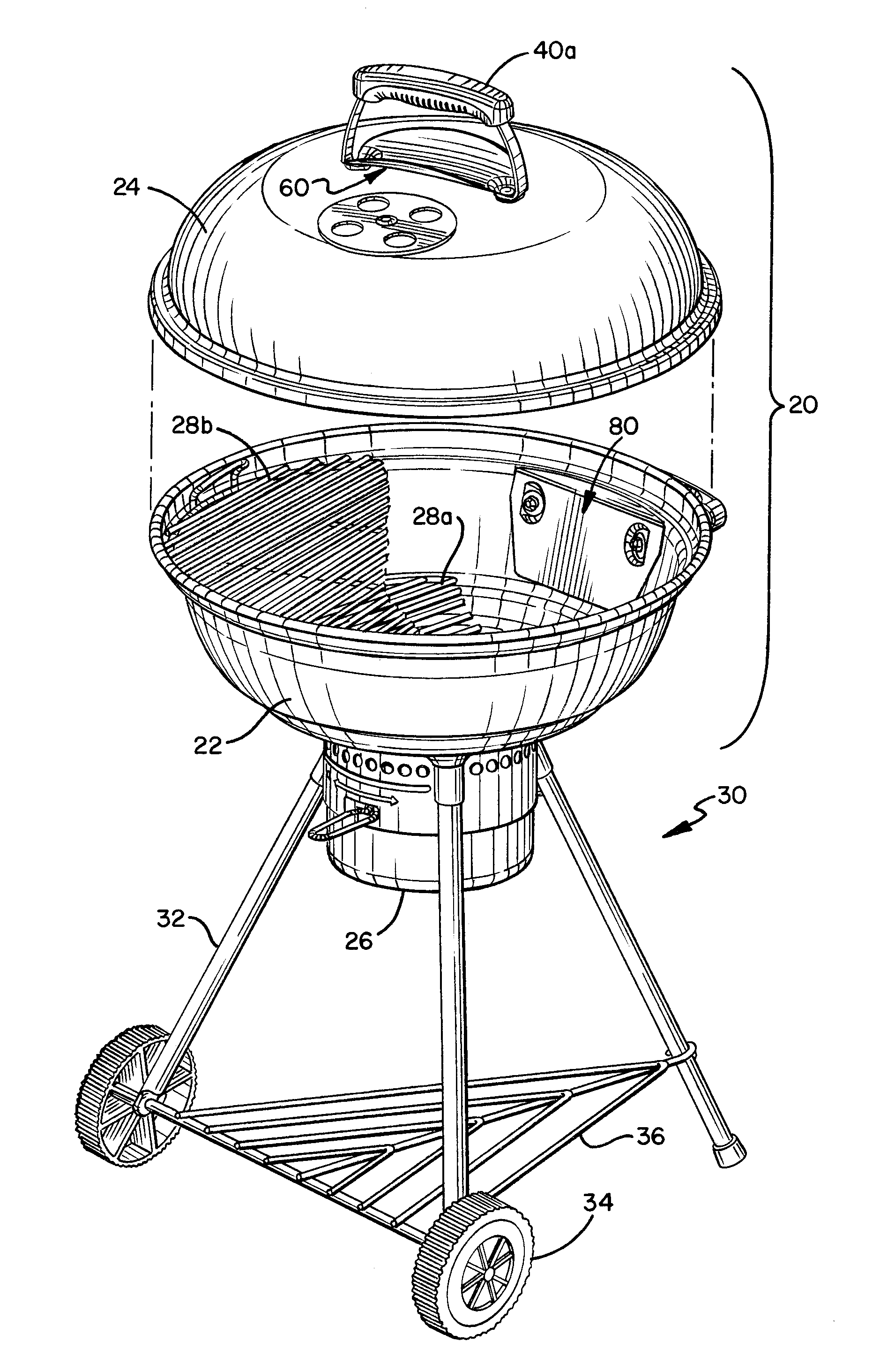
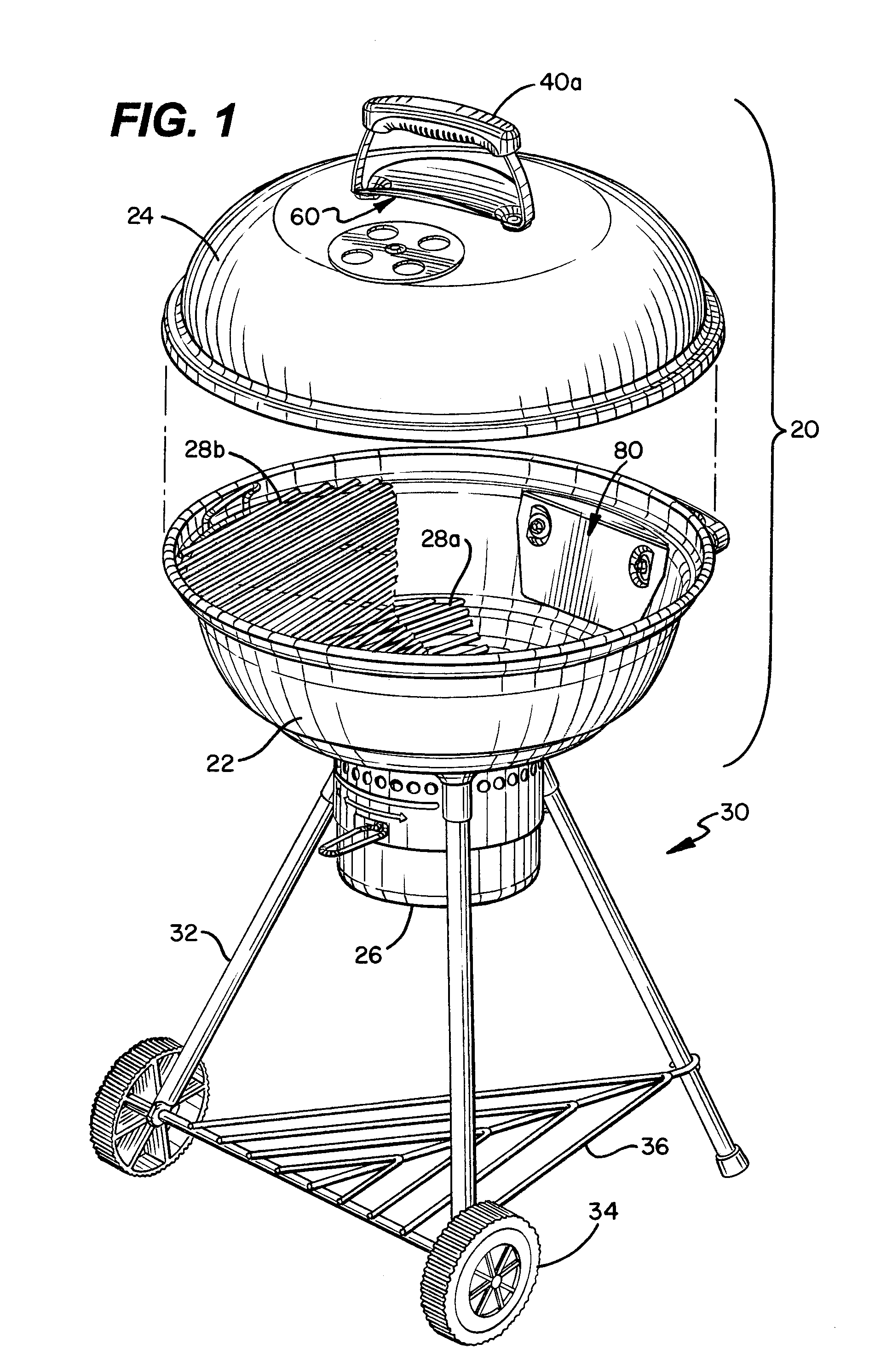
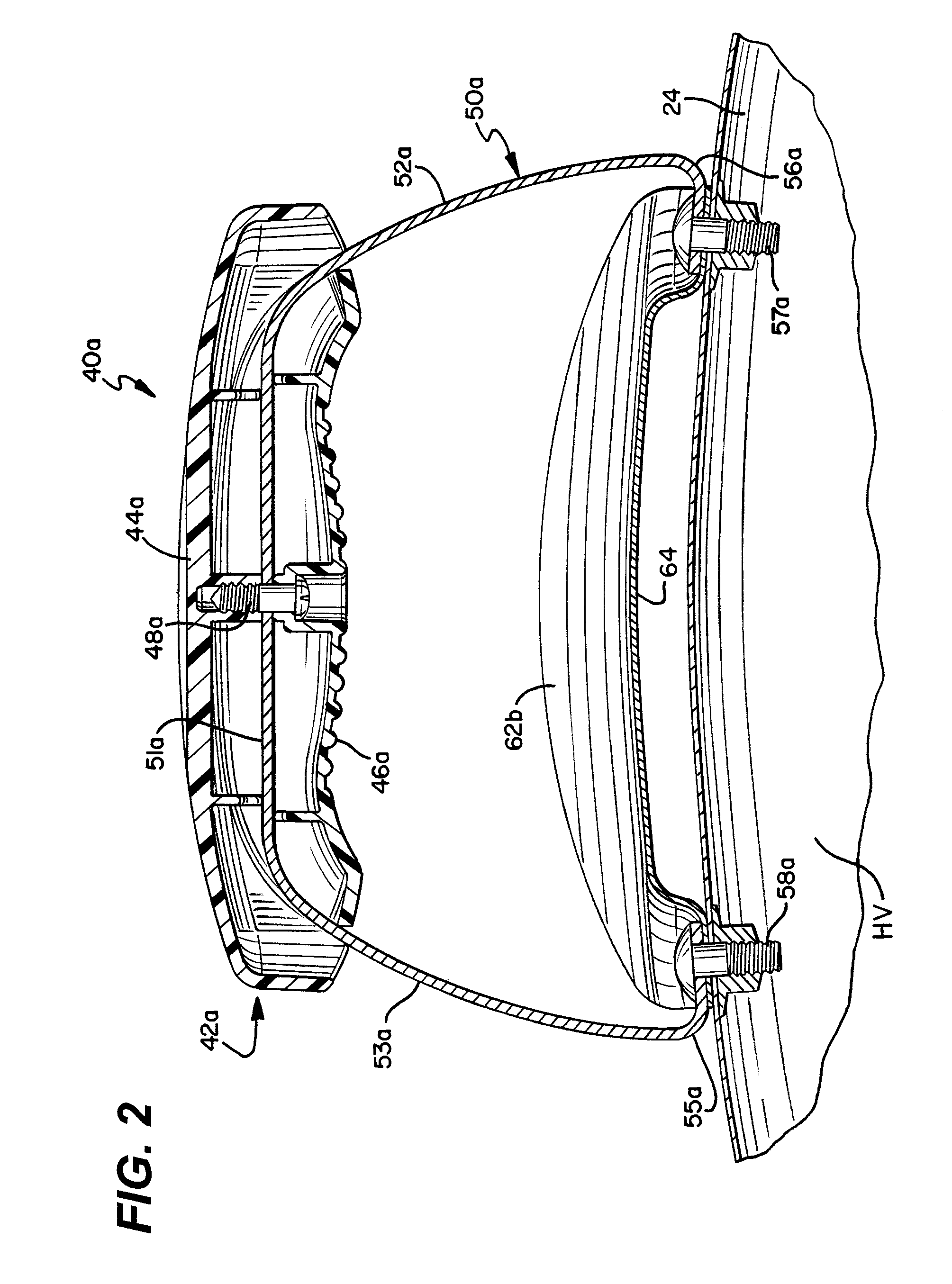
[0025]Turning now to FIGS. 2-3, two cross sectional views are provided which show the heat shield 60 is more detail. As shown, the heat shield 60 is affixed adjacent the outside surface of the lid 24 and is disposed between the outside surface of the lid 24 and the gripping portion 42a of the handle. The heat shield 60 includes apertures which align with the apertures on the handle 40a and the lid 24, whereby the same fasteners 56a, 58a can be used to affix the heat shield 60 to the lid 24. The heat shield 60 has a longitudinal axis which is generally aligned with a length of the gripping portion. When viewed in a cross section plane normal to the longitudinal axis, the heat shield 60 has a generally parabolic shape with two upturned ends 62a, 62b and a vertex 64 that has a spaced positional relationship to the outside surface of the lid 24. Note, however, that the heat shield 60 could be spherical shaped or egg shaped, wherein it would have a single upturned edge that surrounds han...

second embodiment

[0026]Turning now to FIGS. 4-5, a cross sectional view and an exploded view are provided which show the heat shield 80 in more detail. As shown, the heat shield 80 is affixed adjacent the inside surface of the firebowl 22, opposite the handle 40b. The heat shield 80 includes apertures which align with the apertures on the handle 40b and the firebowl 22, whereby the same fasteners 56b, 58b can be used to affix the heat shield 80 to the firebowl 22. Note, however, that additional nuts are provided which are placed between the shield 80 and the firebowl 22, and which act to space the heat shield 80 a distance from the inside surface of the firebowl 22. The heat shield 80 includes a perimetric edge region 52 and a central region 84. The perimetric edge region 82 of the heat shield 80 is in at least close proximity to the inside surface of the firebowl 22 and surrounds the central region of the heat shield. At least of a portion of the central region 84 of the heat shield has a spaced po...


PUM


Abstract

Two main embodiments of a heat shield for a barbecue grill are disclosed herein. Both are designed to reduce the transfer of heat from the heated volume of the cooking chamber to the handle of the barbecue grill. The first embodiment mounts to the exterior of the cooking chamber and is disposed between the cooking chamber and the handle. The first embodiment is contoured to interrupt the convective flow of heated air away from the handle. The second embodiment mounts to the interior of the cooking chamber opposite the handle. The second embodiment rests adjacent the inside surface of the cooking chamber to form a partially or substantially closed volume that serves as an insulating barrier for the handle.

Description

CROSS-REFERENCE TO RELATED APPLICATIONS[0001]Not Applicable.STATEMENT REGARDING FEDERALLY SPONSORED RESEARCH OR DEVELOPMENT[0002]Not Applicable.THE NAMES OF PARTIES TO A JOINT RESEARCH AGREEMENT[0003]Not Applicable.INCORPORATION-BY-REFERENCE OF MATERIAL SUBMITTED ON A COMPACT DISC[0004]Not Applicable.BACKGROUND OF THE INVENTION[0005]1. Technical Field[0006]The embodiments described and claimed herein relate generally to barbecue grill handles. More specifically, some of the embodiments relate to heat barrier structures which reduce the temperature of, and in the region of, barbecue grill handles.[0007]2. Background Art[0008]Barbecue grills are well known in the art. Typically, these barbecue grills include a cooking chamber and a support structure. The cooking chamber can simply comprise an open top firebox, or a combination of a firebox and a lid. In either case, it is typical for barbecue grills to be provided with one or more handles on the cooking chamber, either for moving the ...

Claims


Application Information

Patent Timeline
IPC IPC(8): A47J37/07
CPCA47J37/07A47J45/085A47J37/0786A47J45/062
Inventor GRASSO, JAMESSIEG, EWALDCHOI, CHARLESBRUNO, ANTHONY A.
Owner WEBER-STEPHEN PRODUCTS
Why Eureka
Try Eureka