Reproducible lattice strain measurement method

a lattice strain and measurement method technology, applied in the field of transmission electron microscopy, can solve the problems of increasing the difficulty of controlling the thickness of the sample and the microscope parameters, not keeping pace with the performance improvement of the transistor, and forming bright or dark spots

Inactive Publication Date: 2011-04-14
TEXAS INSTR INC
View PDF0 Cites 10 Cited by
  • Summary
  • Abstract
  • Description
  • Claims
  • Application Information

AI Technical Summary

Benefits of technology

[0008]A method of eliminating errors caused by beam shift (also known as fly-back error) between scan lines is also described.

Problems solved by technology

As integrated circuits are scaling to smaller and smaller dimensions, the transistor performance improvement is not keeping pace.
The electrons in an HRTEM image are coherent and may interfere causing bright or dark spots to form depending upon the thickness of the sample and depending upon microscope parameters (such as depth of focus).
Control of the sample thickness and of the microscope parameters becomes much more difficult as the field of view gets larger.
It is difficult to make reproducible strain measurements using HRTEM images because of the difficulty in reproducible sample preparation and optimization of the microscope parameters.
Small differences in sample to sample thickness may cause significant differences in the measured strain.

Method used


Image

  • Reproducible lattice strain measurement method
  • Reproducible lattice strain measurement method
  • Reproducible lattice strain measurement method

Examples


Embodiment Construction

[0017]The present invention is described with reference to the attached figures, wherein like reference numerals are used throughout the figures to designate similar or equivalent elements. The figures are not drawn to scale and they are provided merely to illustrate the invention. Several aspects of the invention are described below with reference to example applications for illustration. It should be understood that numerous specific details, relationships, and methods are set forth to provide an understanding of the invention. One skilled in the relevant art, however, will readily recognize that the invention can be practiced without one or more of the specific details or with other methods. In other instances, well-known structures or operations are not shown in detail to avoid obscuring the invention. The present invention is not limited by the illustrated ordering of acts or events, as some acts may occur in different orders and / or concurrently with other acts or events. Furth...


PUM

PropertyMeasurementUnit
thicknessaaaaaaaaaa
thicknessaaaaaaaaaa
thicknessaaaaaaaaaa

Abstract

Lattice strain is reproducibly measured using geometric phase analysis (GPA) of a high angle annular dark field mode scanning transmission electron microscope (HAADF-STEM). Errors caused by beam shift (also known as fly-back error) between scan lines are eliminated.

Description

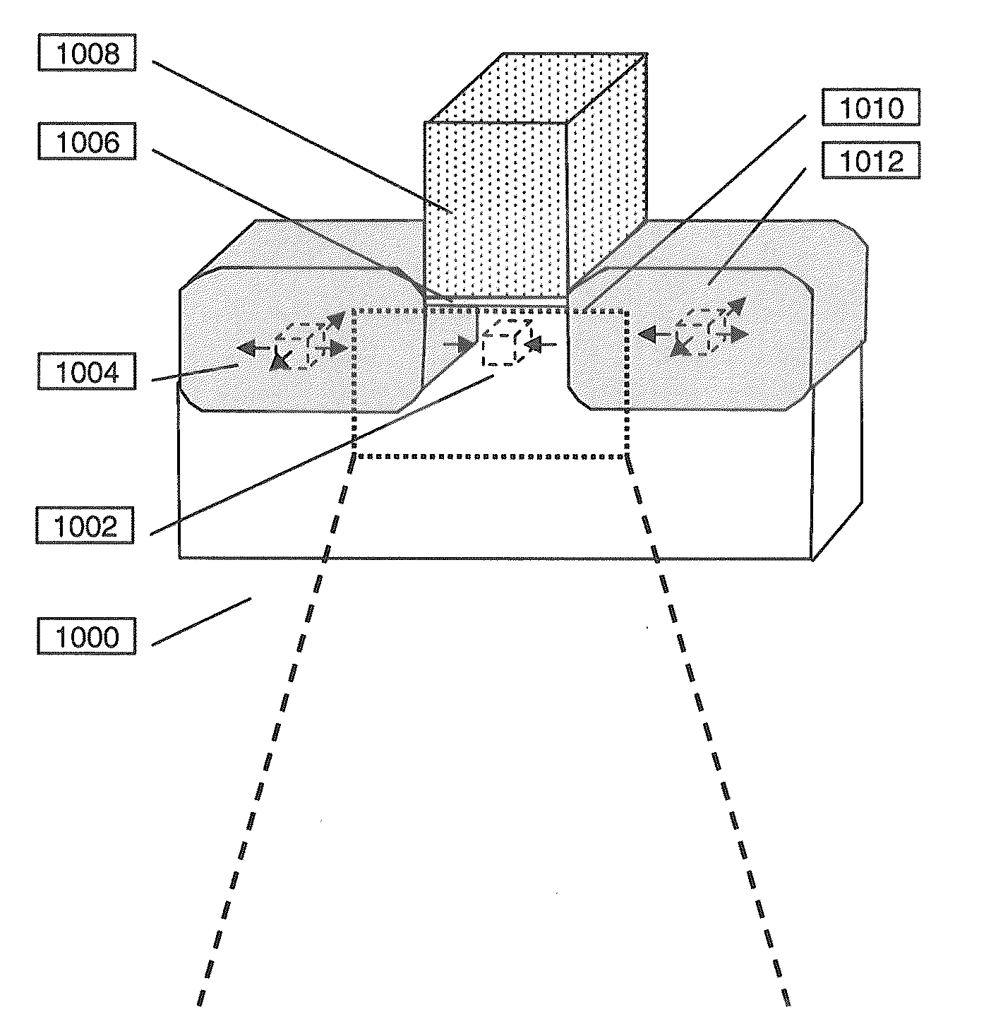
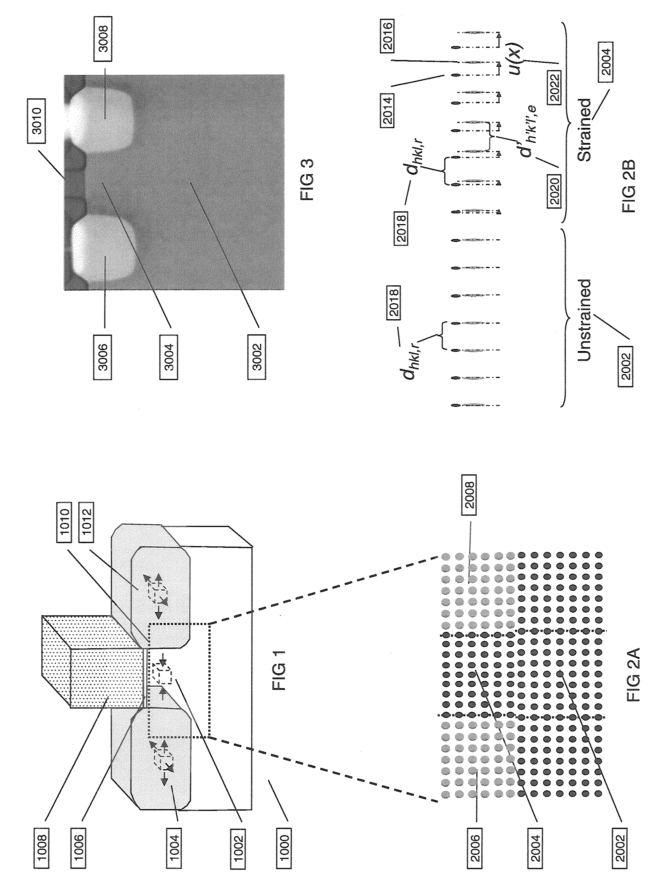
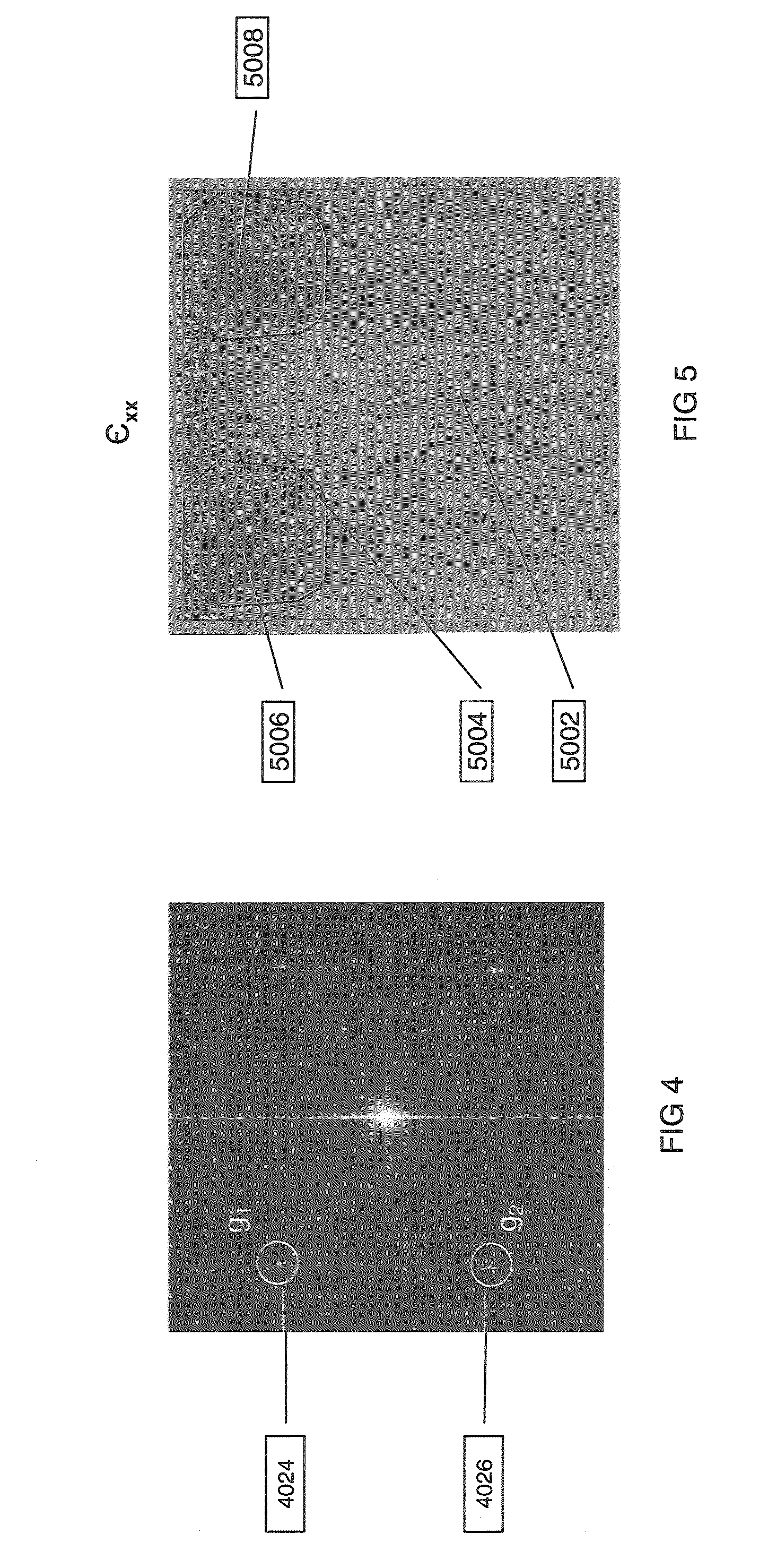
CROSS-REFERENCE TO RELATED APPLICATIONS[0001]This application claims the benefit of priority under U.S.C. §119(e) of U.S. Provisional Application 61 / 249,635 (Texas Instruments docket number TI-67805, filed Oct. 8, 2009.FIELD OF THE INVENTION[0002]This invention relates to the field of transmission electron microscopy (TEM). More particularly this invention relates to the measurement of strain in crystalline materials using TEM.BACKGROUND OF THE INVENTION[0003]As integrated circuits are scaling to smaller and smaller dimensions, the transistor performance improvement is not keeping pace. One method to improve transistor performance is to apply compressive stress to the channel region of PMOS transistors and tensile stress into the channel region of NMOS transistors.[0004]For strained device development a technique that measures the local strain tensor in the channel regions of the device on a routine basis is needed. A commonly used method of measuring lattice strain utilizes a high ...

Claims


Application Information

Patent Timeline
Patent Type & Authority Applications(United States)
IPC IPC(8): G01N23/00
CPCG01N23/20058
Inventor CHUNG, JAYHOONLIAN, GUODA
Owner TEXAS INSTR INC
Why Eureka
Try Eureka