Simplified low insertion force sealing device capable of self restraint and joint deflection

a low insertion force, self-restraint technology, applied in the direction of couplings, cable terminations, transportation and packaging, etc., can solve the problems of bending or deflecting joints, flanged joint systems are costly to install and require considerable maintenance, and the acceptance of fittings, valves, hydrants, etc., to achieve a small increase in insertion force

Active Publication Date: 2011-04-14
MUELLER INT LLC
View PDF102 Cites 7 Cited by
  • Summary
  • Abstract
  • Description
  • Claims
  • Application Information

AI Technical Summary

Benefits of technology

[0025]Another embodiment of the invention is a method of coupling at least two conduits of the invention. The method includes the steps of positioning a sealing device inside a bell coupled to one end of a first conduit, inserting a spigot of a second conduit through the sealing device inside the bell, and partially removing the spigot from the bell. A locking segment of the sealing device engages the outer surface of the spigot as the spigot is partially removed from the bell. The sealing device is adapted to move axially within the bell in the direction of the insertion of the spigot and the movement is assisted by the presence of expansion and contraction grooves in the coupling section of the gasket. This movement allows the locking segment to be displaced from the path of the incoming spigot with little increase in insertion force. The axial movement May be confined to one segment of the sealing device to accommodate angular and radial misalignment of the incoming spigot. The scaling device is adapted to move in the direction of the partially removed spigot from the bell in response to internal hydraulic pressure to effect a seal to the spigot that rests in an angular and radial misaligned position.

Problems solved by technology

There are two related problems in the history of using pipes of any sort, including iron pipes—(1) creating a secure seal to join the pipes and to withstand large pressure, and (2) bending or deflecting the joints of the pipes to meet the intended use of the pipes.
Flanged joint systems are costly to install and require considerable maintenance.
While the push-on type joint has obtained wide acceptance for pipe joints, acceptance for fittings, valves, and hydrants is much lower.
Whether the pipe end is produced in a manufacturing plant or is the result of field cuts required to adjust the length of the pipe, such pipes cannot realistically be beveled or have rounded ends.
Damage to the gaskets or displacement of the gaskets is a likely outcome when inserting a spigot end of a pipe not properly aligned or without a beveled or rounded end into the bell of another push-on joint pipeline component.
Attempts to design low insertion resistance-joints have been made in the past but these designs were not completely satisfactory because normal conical inner surfaces do not allow for sufficient deflection ° Nile bell and socket joint.
Cast iron pipe is rigid and does not permit deflection.
However, that deflection carries an increased risk of loss of pressure.
If the joint is connected into a cone-shaped annulus, deflection of more than a few degrees would degrade the connection opposite the angle of deflection, ultimately leading to a greater potential for a loss of pressure.
Small movements in the earth could, over time, cause leaks in underground piping systems.

Method used


Image

  • Simplified low insertion force sealing device capable of self restraint and joint deflection
  • Simplified low insertion force sealing device capable of self restraint and joint deflection
  • Simplified low insertion force sealing device capable of self restraint and joint deflection

Examples


example

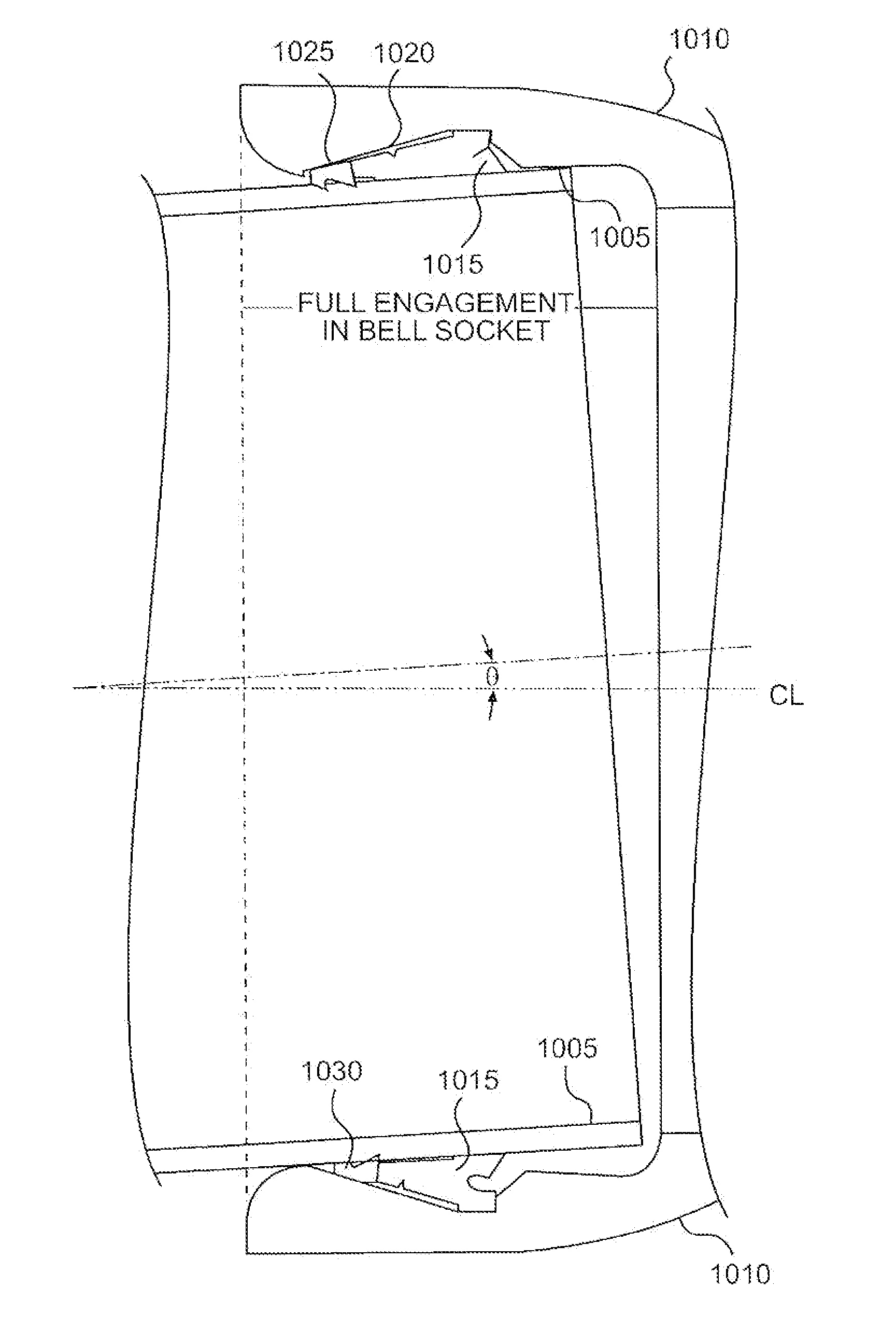
[0073]An experiment using two lengths of 8 inch pipe was conducted. One pipe had a bell as described herein while the other had a spigot as described herein. The two lengths were joined using a sealing device as described herein. The pipes were sealed at their respective open ends and the internal cavity was pressurized. The experiment was conducted first with the pipes having no deflection and then with the pipes having 5.7° and 7.0° of deflection. The results are compiled in Table 1.

TABLE 1No. ofJointMinimumMaximumTestSeg-Deflec-Pressure,Pressure,Numbermentstion, °psipsiTest Result180700772Leak: Gasket Tear280700771Leak: Gasket Tear31407001192Leak: Gasket Tear4100700998.5Leak: Gasket Tear5105.7700828.2Leak: Gasket Tear 6*1407001067.3No failure 7*147.07001028.6Leak from priordamage to gasket*Same gasket was used for Tests 6 and 7. Gasket sustained damage in removal after Test 6.

[0074]If “θ” is defined as the angle of deflection between the axis of the bell socket and the spigot, th...


PUM

PropertyMeasurementUnit
diameteraaaaaaaaaa
diameteraaaaaaaaaa
thicknessaaaaaaaaaa

Abstract

A conduit coupling system, sealing device, bell and method of use are disclosed herein. The system comprises at least two piping components, and a sealing device. A first component has a bell and a second component has a spigot, the spigot is adapted to mate with the bell. The bell comprises a first end and a second end, the first end coupled to the first component. The bell has a concave annular inner surface and a diameter of the annular inner surface adjacent to the first end of the bell is greater than a diameter of the annular inner surface adjacent to the second end of the bell. The sealing device comprises a locking segment comprising a convex outer surface and a K-type gasket coupled to a locking segment or a non-restraining anti-extrusion segment. The sealing device is adapted to fit between the bell and the spigot.

Description

REFERENCE TO RELATED APPLICATIONS[0001]This application claims priority to U.S. provisional application Ser. No. 61 / 250,160, filed Oct. 9, 2009, entitled “Parabolic Ramp Self-Restraining Bell Joint,” and U.S. provisional application Ser. No. 61 / 301,462, filed Feb. 4, 2010, entitled “Simplified Low Insertion Force Sealing Device Capable of Self Restraint and Articulation,” both of which are hereby specifically and entirely incorporated by reference.BACKGROUND[0002]1. Field of the Invention[0003]The invention is directed to couplings and methods of coupling, particularly to bell and spigot couplings and methods. The couplings can be between pipes, fittings, and / or other piping components. The couplings allow for greater pipe deflection and stronger joint retention, with less force needed on insertion.[0004]2. Background of the Invention[0005]Members of the flow control industry, such as producers of pipeline components for the transmission of water, gas, oil, or other fluids have focu...

Claims


Application Information

Patent Timeline
Patent Type & Authority Applications(United States)
IPC IPC(8): F16L21/02F16L17/073
CPCF16L17/035Y10T29/49872F16L37/52F16L37/0845Y10T137/0447
Inventor HOLMES, IV, WILLIAM W.OWEN, WILLIAM H.
Owner MUELLER INT LLC
Why Eureka
Try Eureka