
Method and device for dual-differential sensing

a dual-differential sensing and sensing technology, applied in capacitance measurement, instruments, computing, etc., can solve the problems of device making erroneous judgments, adding this rare shielding layer requires additional cost and design

Active Publication Date: 2011-04-14
EGALAX EMPIA TECH INC
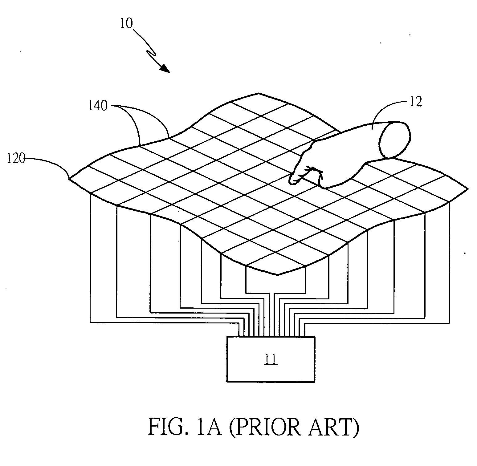
View PDF89 Cites 33 Cited by
  • Summary
  • Abstract
  • Description
  • Claims
  • Application Information

AI Technical Summary

Benefits of technology

[0015]1. providing a dual-differential sensing information to significantly reduce the noise interference; and
[0016]2. when there is a gap between a flexible sensing device and a display, the effect of noise caused by deformation is minimized.
[0019]By aforementioned technical schemes, the present invention achieves at least the following advantages and benefits:
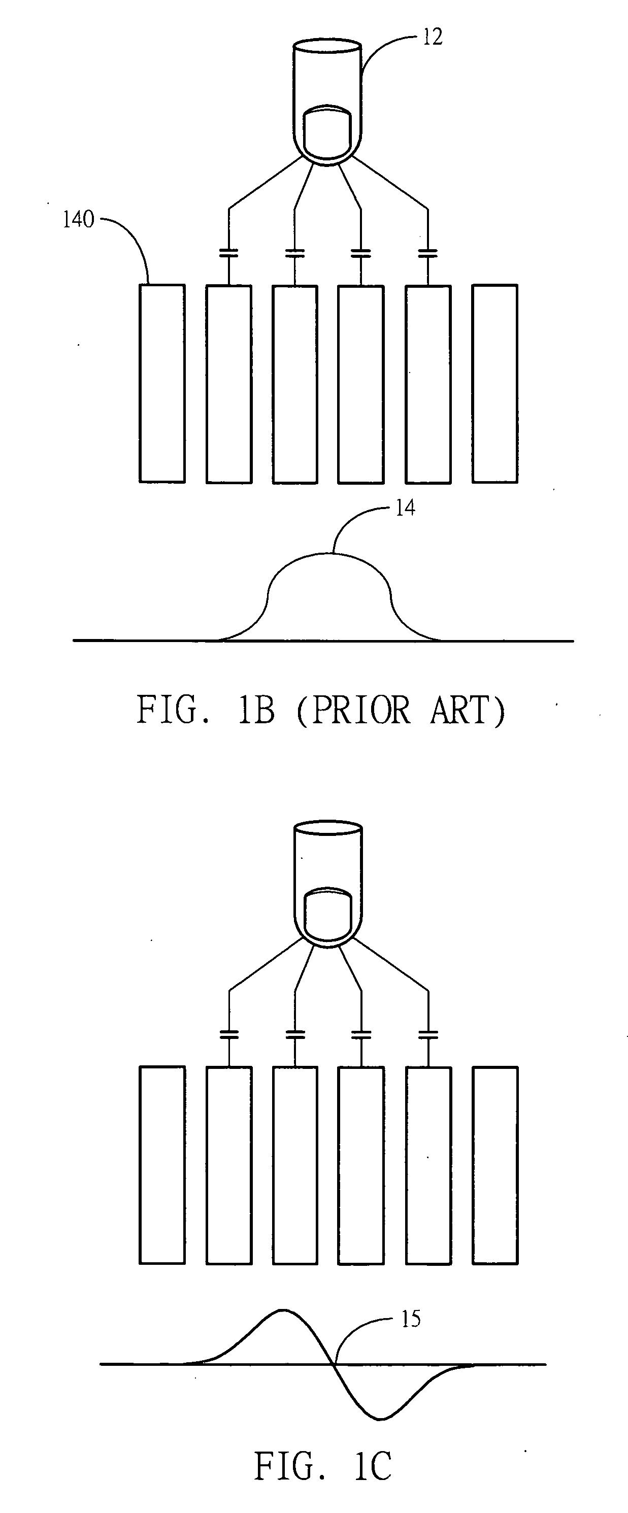
[0020]1. Compared to raw data, differential sensing information can greatly reduce the effect of common mode noise; and
[0021]2. Even if there is no rare shielding layer present between a sensing device and a display, the differential sensing information can greatly reduce the effect of noise caused by deformation, thereby preventing misjudgments.

Problems solved by technology

As noted previously, when a display is functioning, its surface will emit large amount of noise that interferes with the sensing device on the display, and causes the sensing device to make erroneous judgments.
However, the addition of this rare shielding layer requires additional cost and design.

Method used


Image

  • Method and device for dual-differential sensing
  • Method and device for dual-differential sensing
  • Method and device for dual-differential sensing

Examples


first embodiment

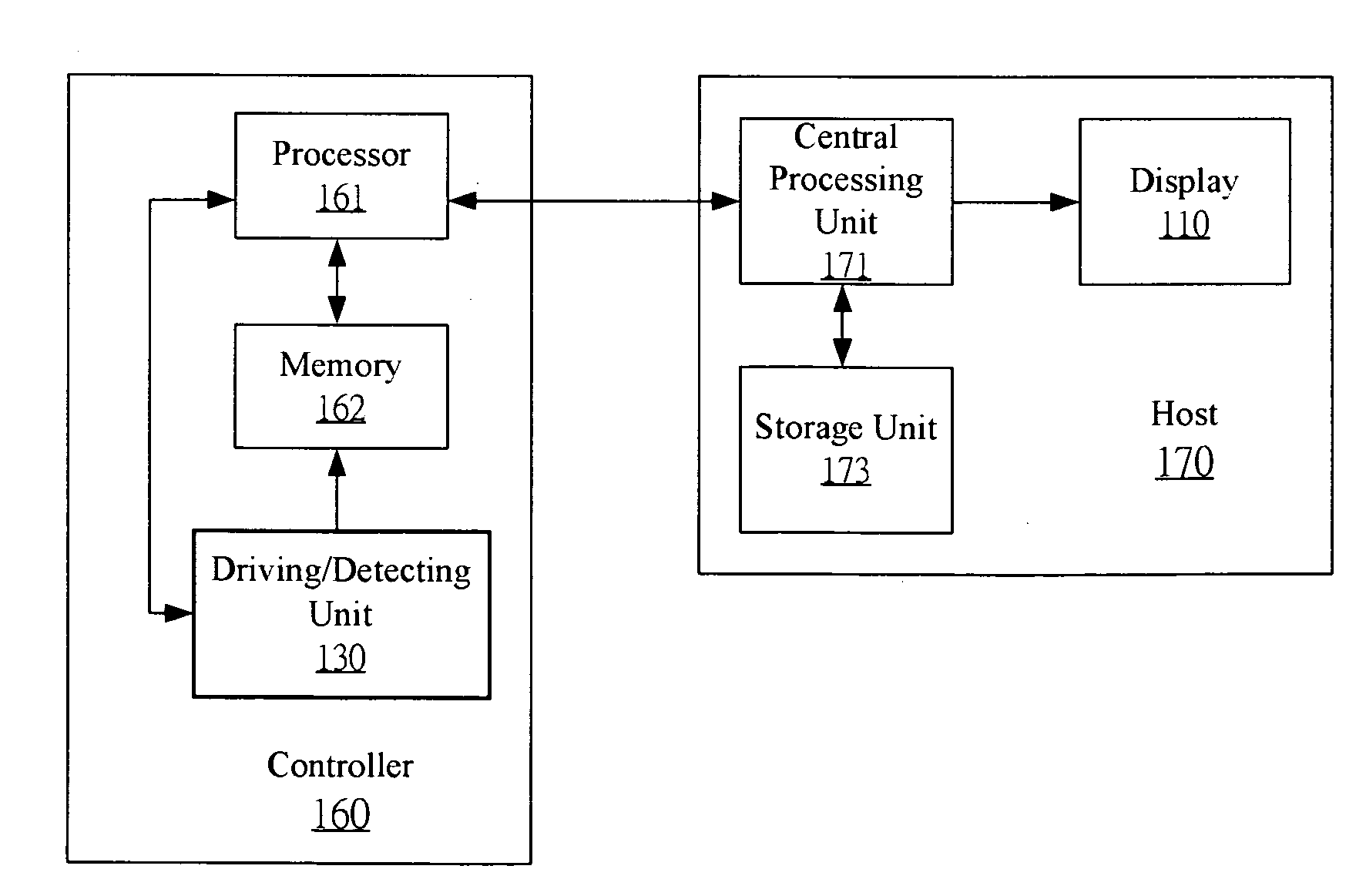
[0141]In the best mode, referring to FIG. 5, a method for dual-differential sensing according to the present invention is illustrated. First, in step 510, a sensing device with a plurality of sensors is provided. Then, in step 520, a sensing information is obtained, each value of the sensing information corresponds to signals of three sensors in the plurality of sensors. Thereafter, in step 530, a location touched or approached by an external object on the sensing information is determined based on the sensing information.

[0142]In a first example of the present invention, the sensing information can be obtained by a dual-differential circuit, which includes: a first-stage differential circuit, a second-stage differential circuit and a measuring circuit, as shown in FIG. 3D, 3I or 3J.

[0143]The first-stage differential circuit includes a pair or a plurality of first subtractors (e.g. differential amplifiers in switching circuits 325). Each of first subtractors generates a first-stage ...

second embodiment

[0158]Referring to FIG. 6, a sensing method for a flexible sensing device according to the present invention is provided. First, in step 610, a flexible sensing device with a plurality of sensors is provided on a display, the effect of noise on signals of each sensor corresponds to the distance between the sensor and the display. Then, in step 620, a sensing information is obtained, the effect of noise on each value of the sensing information corresponds to the distances between three sensors and the display.

[0159]Referring to FIG. 7A, sensing device 120 is a flexible sensing device. When untouched, the distances between various parts of second sensing layer 120B on sensing device 120 and display 110 are uniform at a distance d1. When touched, sensing device 120 will deform. The degree of deformation varies with pressure, such that the distances between various parts of second sensing layer 120B on sensing device 120 and display 110 are no longer uniform. For example, the distances ...


PUM


Abstract

A method and device for dual-differential sensing is disclosed. The sensing information can be generated from signals provided by a sensing device with a plurality of sensors. Each value of the sensing information corresponds to signals of three sensors, respectively. The sensing device is flexible and configured on a display. The noise effect of the display on the signal of each sensor corresponds to the distance between the display and the sensor. Besides, the noise effect of the display on each value of the sensing information corresponds to the distances between the display and the three sensors, respectively.

Description

CROSS REFERENCE TO RELATED APPLICATIONS[0001]This application claims the benefit of U.S. Provisional Application No. 61 / 298,252, filed on Jan. 26, 2010, Provisional Application No. 61 / 298,243, filed on Jan. 26, 2010 and U.S. Provisional Application No. 61 / 250,051, filed on Oct. 9, 2009, which is herein incorporated by reference for all intents and purposes.BACKGROUND OF THE INVENTION[0002]1. Field of the Invention[0003]The present invention relates to a method and device for touch sensing, and more particularly, to a sensing method and device for providing dual-differential sensing information.[0004]2. Description of the Prior Art[0005]Touch displays have been widely used in the various electronic devices. One approach is to employ a touch sensitive panel to define a 2-D touch area on the touch display, where sensing information is obtained by scanning along horizontal and vertical axes of the touch panel for determining the touch or proximity of an external object (e.g. a finger) o...

Claims


Application Information

Patent Timeline
IPC IPC(8): G06F3/041
CPCG06F3/0416G06F3/044G06F3/0418G06F3/047G06F3/0412G06F2203/04104G06F2203/04111G01R27/2605G06F2203/04103G06F2203/04102G06F3/04166G06F3/04182G06F3/0445G06F3/0446G06F3/041
Inventor CHANG, CHIN-FULEE, CHENG-HANTANG, CHI-HAOHO, SHUN-LUNG
Owner EGALAX EMPIA TECH INC
Learn More