Display system, screen and projector

Inactive Publication Date: 2011-04-14
SEIKO EPSON CORP
View PDF5 Cites 8 Cited by
  • Summary
  • Abstract
  • Description
  • Claims
  • Application Information

AI Technical Summary

Benefits of technology

[0011]An advantage of some aspects of the invention is to provide a screen, a projector and a display system, in which the high scattering pr

Problems solved by technology

In the techniques of the patent documents 1 and 2, there is a problem to be improved in view of compatibility between the image quality and the transparency.
When the transparency is raised, since the viewing angle is narrowed and it becomes hard to observe the image, the image quality is deteriorated.
Besides, when invisible light resulting from external light is incident on the wavelength selection film from the opposite side to the p

Method used


Image

  • Display system, screen and projector
  • Display system, screen and projector
  • Display system, screen and projector

Examples


Example

First Embodiment

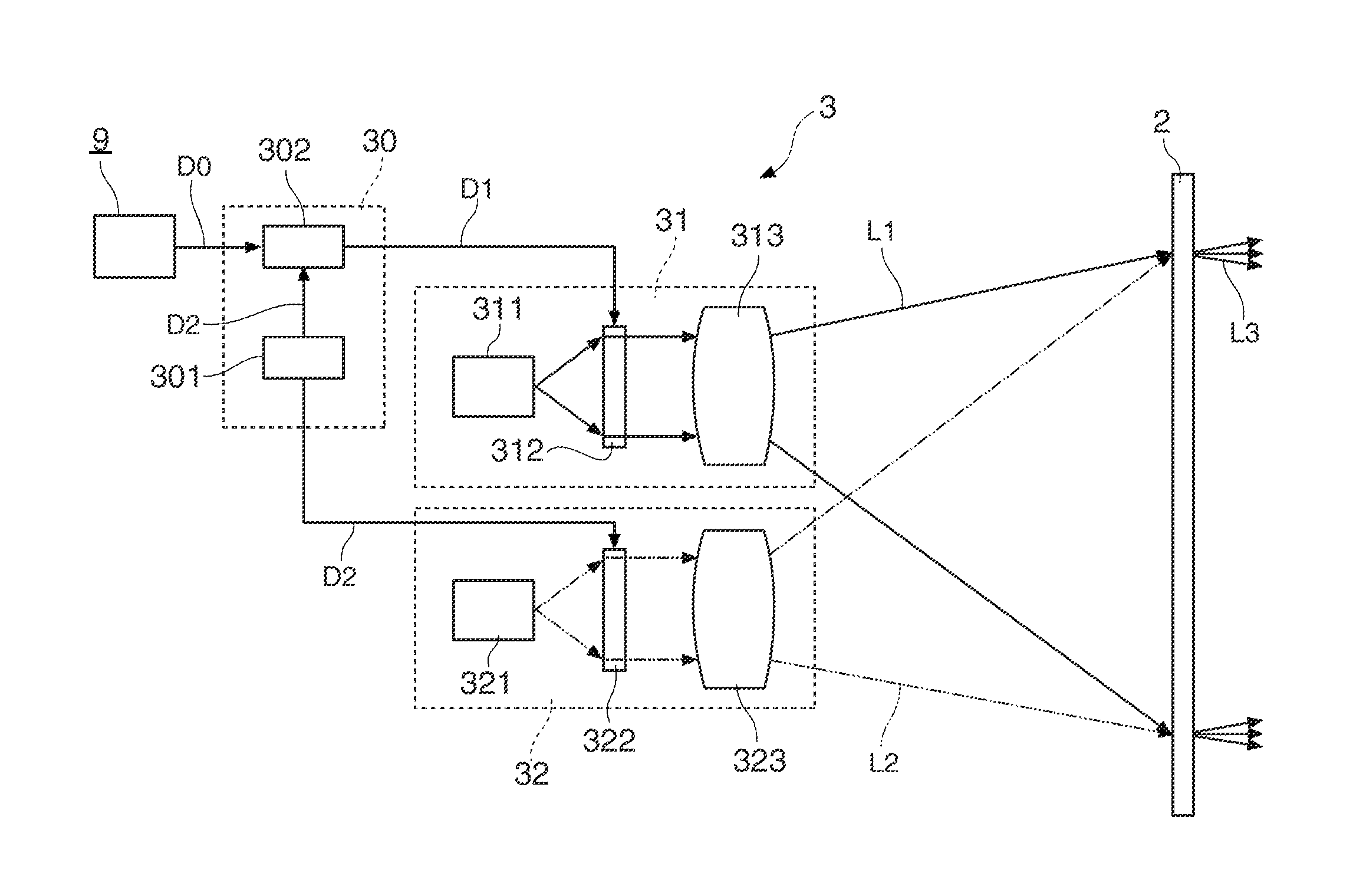
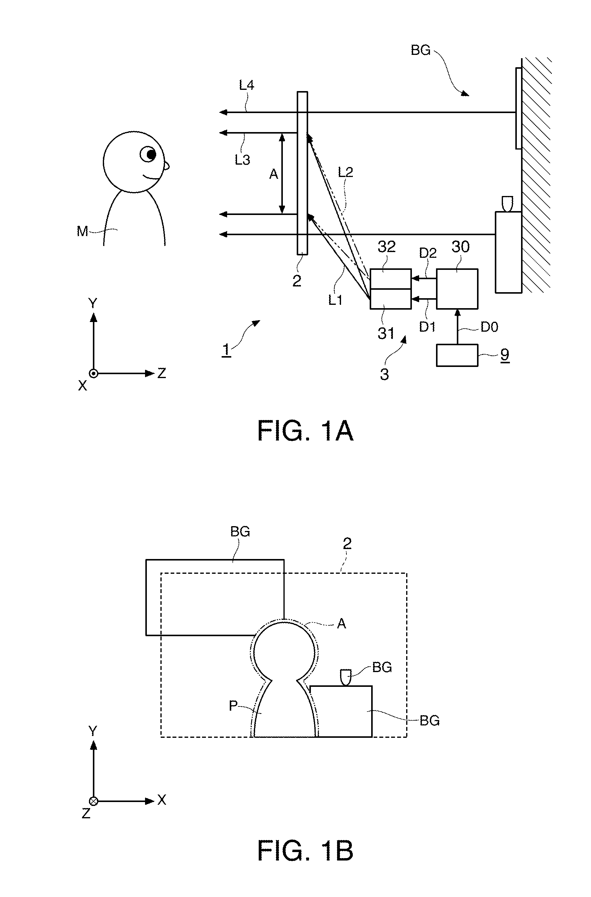
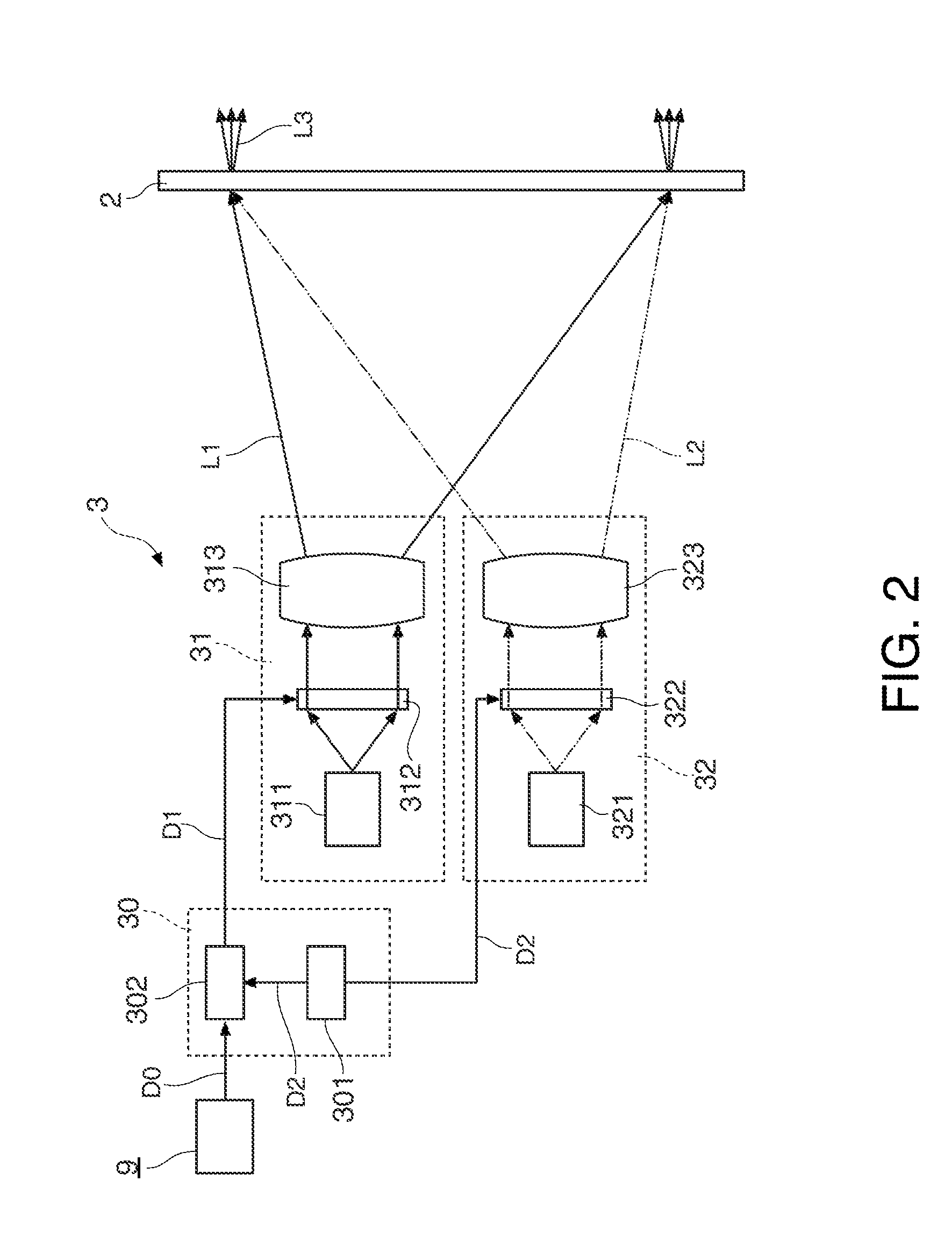
[0056]FIG. 1A is a schematic view showing a schematic structure of a display system 1 of a first embodiment, and FIG. 1B is a view showing a use example of the display system 1. As shown in FIGS. 1A and 1B, the display system 1 includes a screen 2 and a projector 3. The projector 3 includes a data supply section 30, an image projection system 31 and an invisible light projection system 32. The screen 2 is the screen to which the invention is applied, and the projector 3 is the projector to which the invention is applied.

[0057]In an XYZ orthogonal coordinate system shown in FIGS. 1A and 1B, directions along the principal plane of the screen 2 are an X direction and a Y direction, and a normal direction of the principal plane of the screen 2 is a Z direction. The X direction and the Z direction are, for example, the horizontal direction, and the Y direction is, for example, the vertical direction.

[0058]The display system 1 of the first embodiment roughly operates as de...

Example

Second Embodiment

[0093]Next, a display system of a second embodiment will be described with reference to FIGS. 5A and 5B.

[0094]FIG. 5A is a schematic view showing a schematic structure of a display system 1B of the second embodiment, and FIG. 5B is an enlarged sectional view showing a structure of the screen 2B. The display system 1B is different from the first embodiment in that an image projection system 31B is constructed as an apparatus independent of an invisible light projection system 32.

[0095]The image projection system 31B projects an image light L1 onto a screen 2B based on image data D2 supplied from a signal source 9. The image projection system 31B is constructed of, for example, a projection-type or scanning-type projector. The image projection system 31B can be constructed of a normal projector.

[0096]The invisible light projection system 32 projects an address light L2 onto the screen 2B based on range data D1 supplied from the signal source 9. The invisible light pro...

Example

Third Embodiment

[0100]Next, a display system of a third embodiment will be described. The third embodiment is different from the first and the second embodiments in that a screen includes a light absorption layer to absorb a complementary light which has a complementary color in subtractive color mixing with respect to a color light absorbed in a photoconductive layer.

[0101]FIG. 6A is an enlarged sectional view showing a structure of a screen 2C in the display system of the third embodiment, and FIG. 6B is a graph showing light absorption spectra of a photoconductive layer and a light absorption layer. The horizontal axis of the graph shown in FIG. 6B indicates the wavelength, and the vertical axis indicates the transmittance.

[0102]As shown in FIG. 6A, the screen 2C includes a light absorption layer 27. The light absorption layer 27 is formed on the surface of a transparent substrate 21 on the opposite side to a transparent electrode 23. The light absorption layer 27 is constructed ...


PUM

PropertyMeasurementUnit
Coloraaaaaaaaaa
Areaaaaaaaaaaa
Photoconductivityaaaaaaaaaa

Abstract

A display system includes: a screen in which, in an area on which invisible light is incident, a scattering state where visible light is scattered and a transmission state where visible light is transmitted are switched; an image projection system to project an image of the visible light onto the screen; and an invisible light projection system to project the invisible light onto the screen and to cause an area of the screen onto which a desired portion of the image is projected to have the scattering state.

Description

[0001]The entire disclosure of Japanese Patent Application No. 2009-234286, filed Oct. 8, 2009 is expressly incorporated by reference herein.BACKGROUND[0002]1. Technical Field[0003]The present invention relates to a display system, a screen and a projector.[0004]2. Related Art[0005]Hitherto, there is known a technique in which an image is displayed on a screen by a projector or the like. In recent years, a technique is proposed in which an image light is diffused and scattered by a transparent screen and an image is displayed. When this technique is used, a person or a physical body in an actual space where the screen is arranged is observed through the screen, and the image can be assimilated to the actual space.[0006]For example, when information relating to a window-displayed exhibit is projected on the window glass, the information can be effectively displayed without disturbing the observation of the exhibit. At a bank window or the like, when information of a visitor is displa...

Claims


Application Information

Patent Timeline
IPC IPC(8): G02F1/1335G02F1/13G02F1/1334G02F1/135G03B21/00G03B21/62H04N5/74
CPCG02F1/1334G02F1/133509G02F1/1354G02F2001/1351G02F2001/1352H04N9/3102G02F2203/11G02F2203/34G03B21/00G03B21/56G03B21/62G02F2201/08G03B21/005G02F1/1351G02F1/1352
Inventor YAMAUCHI, TAISUKE
Owner SEIKO EPSON CORP
Why Eureka
Try Eureka