
Insufflation gas heater system and tubing for use therewith

a technology of insufflation gas and heater system, which is applied in the field of instruments and methods used in minimally invasive surgery, can solve the problems of limited heat up, high cost of existing sets, and unheated co/sub>2 entering the patient, so as to or operations, reduce waste, and reduce the cost of disposable sets

Active Publication Date: 2011-04-14
TEMPLE JOHN
View PDF8 Cites 9 Cited by
  • Summary
  • Abstract
  • Description
  • Claims
  • Application Information

AI Technical Summary

Benefits of technology

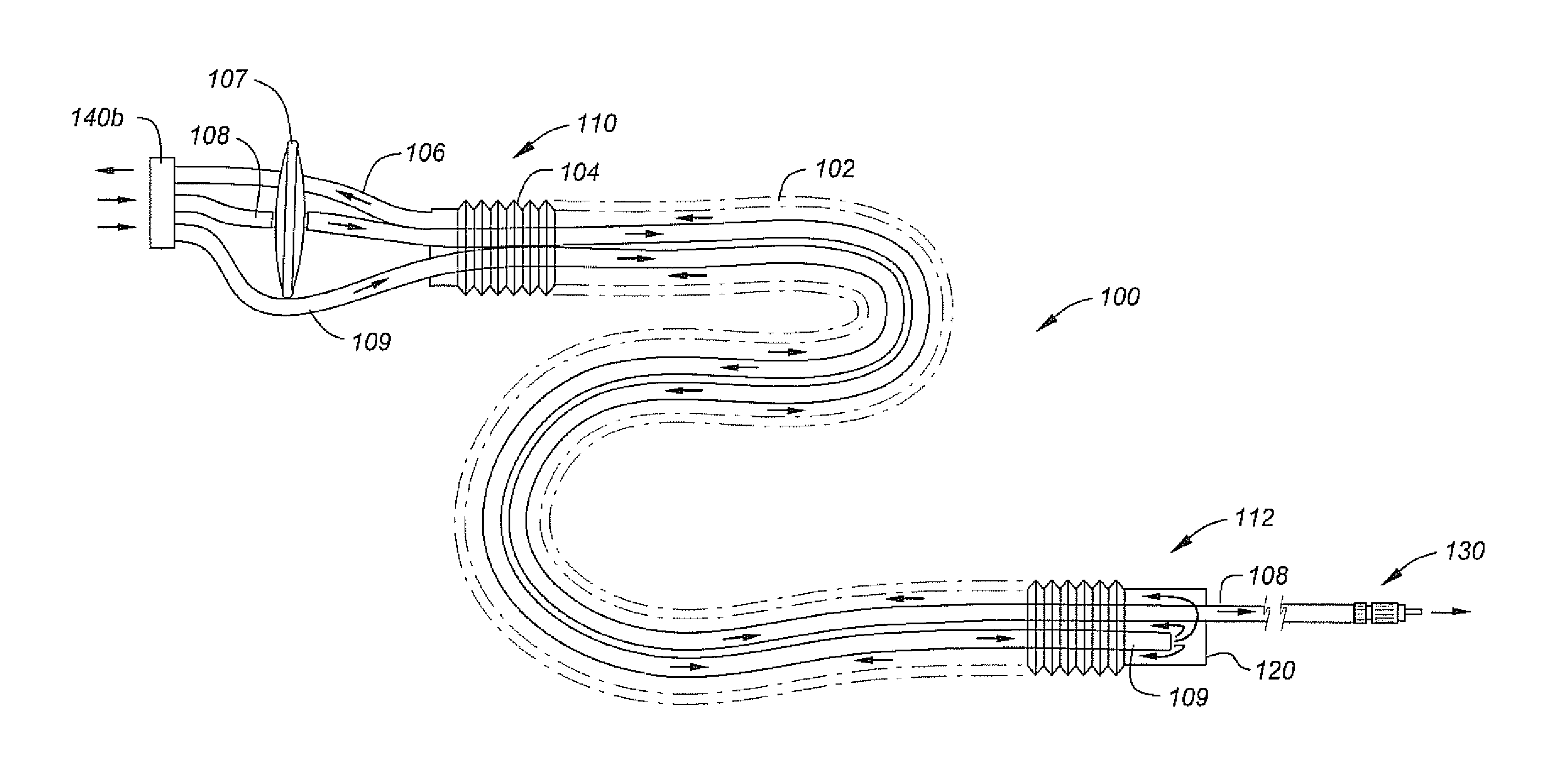
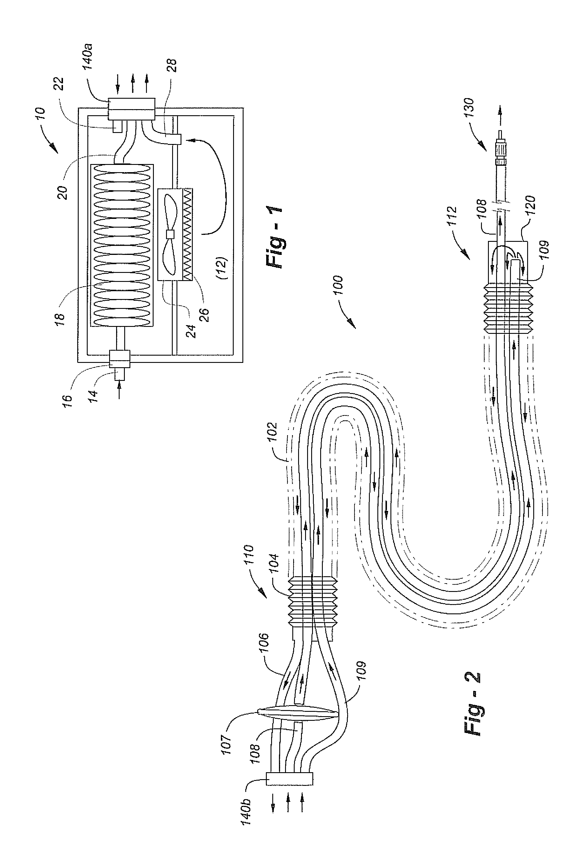
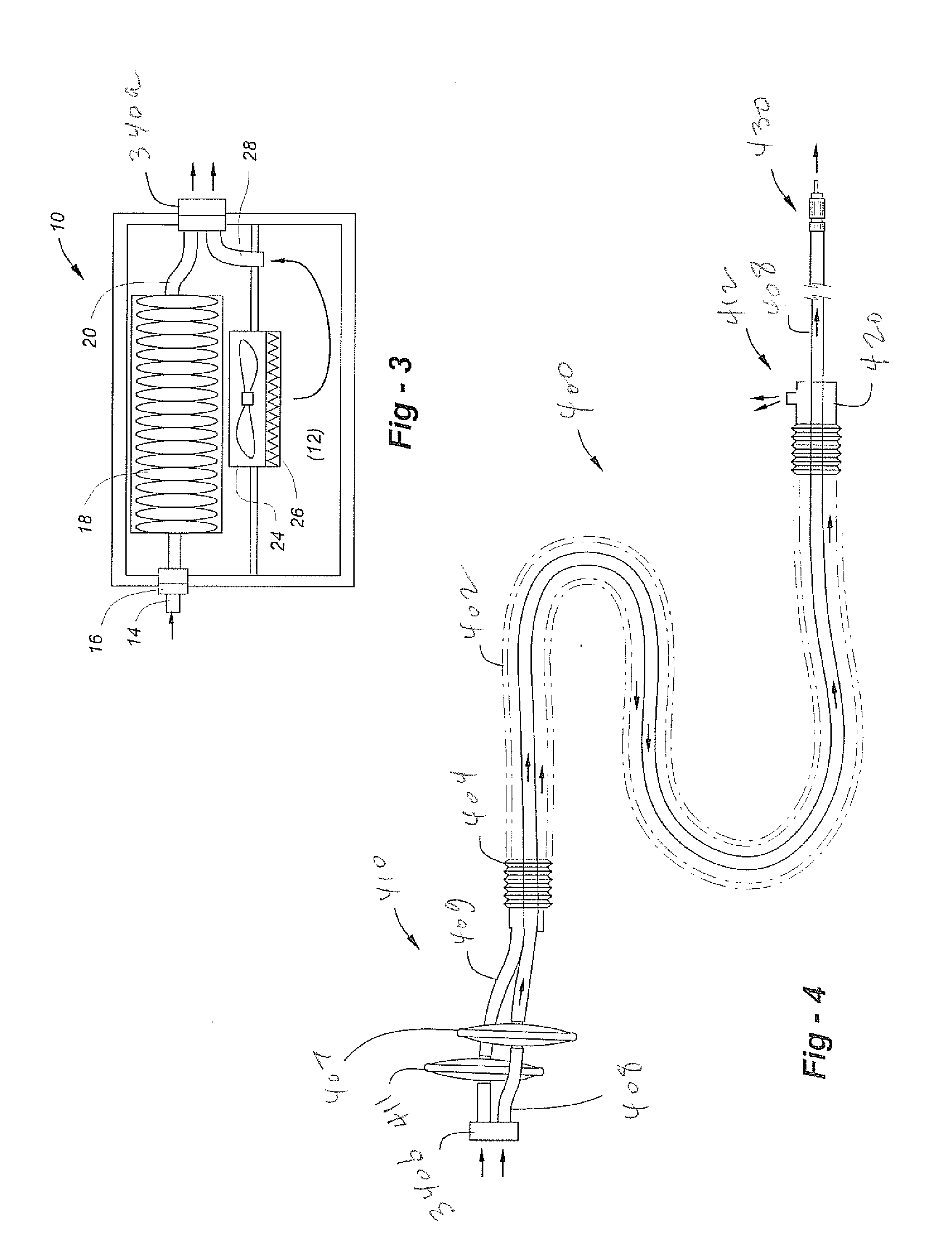
[0010]This invention improves upon existing insufflation gas heaters through the use of a warming gas which flows through a jacket to heat an insufflation gas flowing in a separate tube, thereby reducing waste the cost of the equipment involved. Since the CO2 does not flow directly over a heater such as a resistance wire as it travels from an insufflator to a patient, the heating element (and sensors) may separate from the disposable unit of a heated insufflation set, thereby reducing disposable waste. The heating element and sensors also need not be cleaned or re-sterilized prior to, or after, use in surgery, which reduces the cost of production of the disposable set and or the operation. Moreover, the heat is constantly maintained, thereby eliminating “cold spots” caused by the natural cycling of the resistance heaters due to the nature of the operation being preformed on the patient.

Problems solved by technology

There are several drawbacks to these existing approaches.
With the flow of cold CO2, the controller delivers power to the resistance heater, and while this may occur rapidly, heat-up is limited by the need to avoid over heating which could burn the patient.
Often times this results in unheated CO2 entering the patient.
Also existing sets are very expensive, as the heating element in all of the sets is disposable.

Method used


Image

  • Insufflation gas heater system and tubing for use therewith
  • Insufflation gas heater system and tubing for use therewith
  • Insufflation gas heater system and tubing for use therewith

Examples


Embodiment Construction

[0018]This invention relates to instruments and methods used in minimally invasive surgery (MIS) and, in particular, to apparatus and methods using a warming gas for heating insufflation gas of the type used in laparoscopic procedures. In all preferred embodiments, the insufflation gas is carbon dioxide and warming gas is air.

[0019]One embodiment of the invention uses two remote heaters; one to heat the CO2 insufflation gas to body temperature prior to entering the patient, and a second heater to control a circular flow of warming gas (i.e., room air) in a jacketed tubing assembly to heat the insufflation gas. The heaters may both run at a constant temperature of approximately 98° F. (i.e., 98±7°). As such, heat entering the body will be approximately 98° because the CO2 has been preheated and heat is not allowed to escape into the atmosphere though the tubing walls.

[0020]As an alternative to a separate heater for the insufflation gas, a single heater for the warming gas may be prov...


PUM


Abstract

A warming gas flows through a jacket to heat an insufflation gas flowing in a separate tube, thereby reducing cost and disposable waste. The heated warming gas may be filtered to sterilize or maintain sterility and released to atmosphere after heating the flowing insufflation gas. Alternatively the warming gas may be reheated and recirculated through the jacket, with an additional tube being used within the jacket so that the warming gas flows in both directions lengthwise. The insufflation gas may be carbon dioxide and the warming gas may be room air. The heating element and sensors may be separate from the disposable unit of a heated insufflation set, and need not be re-sterilized prior to or after use in surgery. The heat is constantly maintained, thereby eliminating “cold spots” caused by the natural cycling of the resistance heaters due to the nature of the operation being preformed on the patient.

Description

REFERENCE TO RELATED APPLICATION[0001]This application claims priority from U.S. Provisional Patent Application Ser. No. 61 / 250,144, filed Oct. 9, 2009, the entire content of which is incorporated herein by reference.FIELD OF THE INVENTION[0002]This invention relates generally to instruments and methods used in minimally invasive surgery and, in particular, to apparatus and methods for heating insufflation gas of the type used in laparoscopic procedures.BACKGROUND OF THE INVENTION[0003]Laparoscopic surgery, also called minimally invasive surgery (MIS) is a recent development in which operations in the abdominal or pelvic cavities, for example, are performed through small incisions (usually 0.5-1.5 cm) as compared to larger incisions associated with “open” surgical procedures. Laparoscopic procedures typically use images displayed on TV monitors for magnification of the surgical elements as oppose to direct visualization by the surgeon.[0004]There are a number of advantages to the pa...

Claims


Application Information

Patent Timeline
IPC IPC(8): A61M13/00
CPCA61M13/003A61M2202/0225A61M13/00A61M2205/3368A61M2205/3653A61M2205/3331A61M13/006
Inventor TEMPLE, JOHN
Owner TEMPLE JOHN
Learn More