
Method for guiding symmetric implantation of bone screws

a symmetric implantation and bone screw technology, applied in the field of guiding symmetric implantation of bone screws, can solve the problems that the surgeon cannot solve the problems of the surgeon, and the implantation path during the operation may deviate from the one previously conceived by the surgeon, so as to increase the success rate of the implantation of the pedicle screw

Inactive Publication Date: 2011-04-14
ACCUMIS
View PDF1 Cites 0 Cited by
  • Summary
  • Abstract
  • Description
  • Claims
  • Application Information

AI Technical Summary

Benefits of technology

[0009]The present invention provides a method for guiding symmetric implantation of bone screws, embodies the notion of computer-aided surgery, and applies to a surgical guidance system for use with pedicle screw placement. The method involves generating a second implanting information that is based on and symmetric to a first implanting information of a first bone screw, so that bone screws implanted in two sides of a spinous process are precisely aligned with each other in the same transverse section of the spinous process. Thus, the forces exerted on the two sides of the spinous process are equal, the bone screws are prevented from loosening, dislocating, or breaking, and as a consequence, the success rate of pedicle screw placement is significantly improved.
[0013]2. The implanting information of a bone screw to be implanted on the other side of a spinous process is generated by a mirroring process so that bone screws flanking the spinous process can be implanted in the same transverse section of the spinous process. As a result, the forces exerted on the two sides of the spinous process are equal so as to prevent the bone screws from loosening, dislocating, or breaking, and therefore the success rate of pedicle screw placement is increased.

Problems solved by technology

However, the absolute and relative positions of the vertebrae during operation are likely to differ from those shown by pre-operative CT scanning, and thus the implantation paths during operation may deviate from those previously conceived by the surgeon.
The problems can only be solved by the surgeon's professional judgment and ample experience.

Method used


Image

  • Method for guiding symmetric implantation of bone screws
  • Method for guiding symmetric implantation of bone screws
  • Method for guiding symmetric implantation of bone screws

Examples


Embodiment Construction

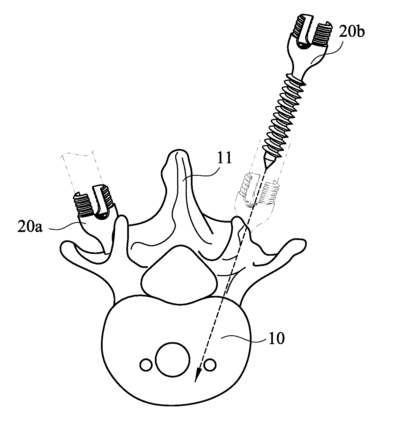
[0019]Please refer to FIG. 3 for a flowchart of a method for guiding symmetric implantation of bone screws according to an embodiment of the present invention. The method is applicable to a surgical guidance system for use with pedicle screw placements and includes the steps of: providing a spinal image (S10); obtaining a first implanting information (S20); setting a reference line in the spinal image (S30); generating a second implanting information by mirroring (S40); and guiding a bone screw according to the second implanting information (S50).

[0020]Please refer to FIG. 4A through FIG. 4D for the flowchart of the steps illustrated corresponding to FIG. 3. More specifically, FIG. 4A corresponds to steps S10 and S20 shown in FIG. 3 while FIGS. 4B, 4C, and 4D correspond to steps S30, S40, and S50, respectively.

[0021]At the step of providing a spinal image (S10), as shown in FIG. 4A, an image of a spine 10 is provided. The spine 10 has a first bone screw 20a implanted in one side of ...


PUM


Abstract

A method for guiding symmetric implantation of bone screws is provided. The method includes the steps of: providing a spinal image of a spine, wherein the spine has a first bone screw implanted in one side of a spinous process of the spine; obtaining a first implanting information of the first bone screw; setting a reference line in the spinal image; generating a second implanting information by mirroring the first implanting information with respect to the reference line; and guiding a second bone screw to be implanted in the other side of the spinous process according to the second implanting information. The method generates a second implanting information that is based on and symmetric to the first implanting information, thus allowing the bone screws to be precisely implanted in both sides of the spinous process and aligned with each other in the same transverse section of the spinous process.

Description

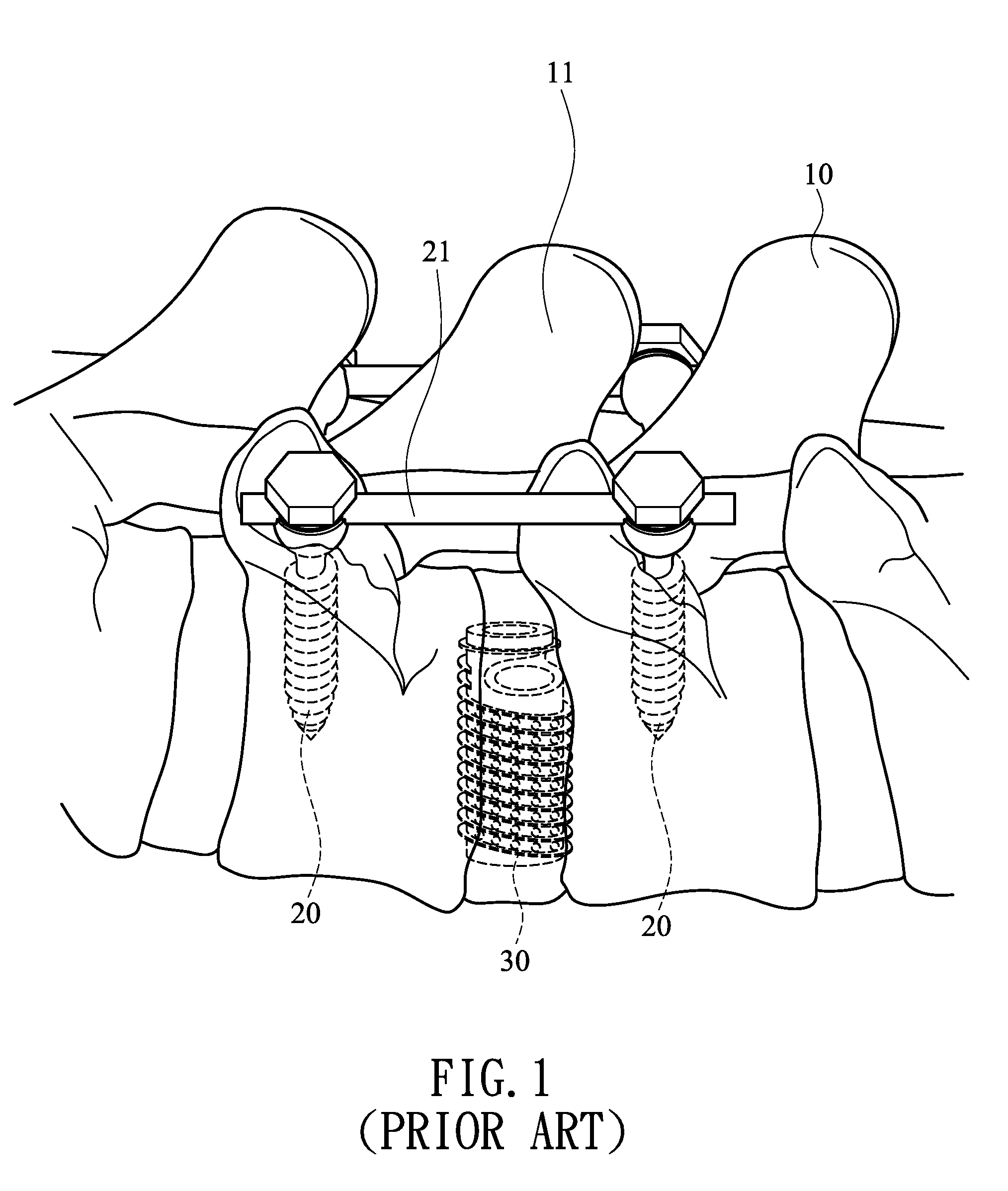
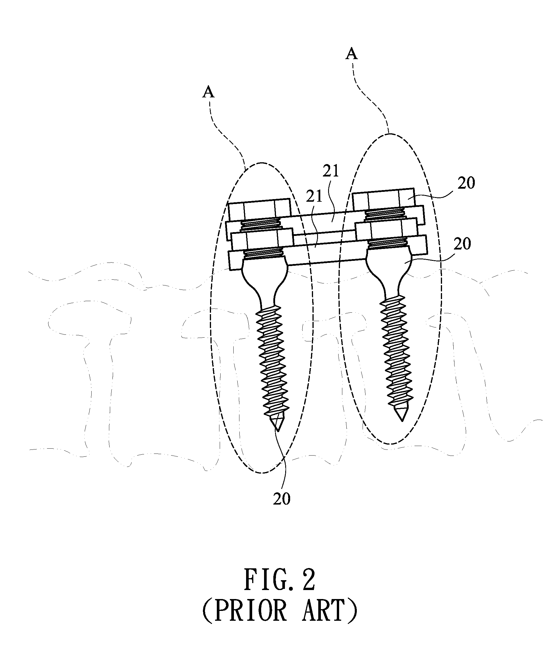
BACKGROUND OF THE INVENTION[0001]1. Technical Field[0002]The present invention relates to methods for guiding symmetric implantation of bone screws and, more particularly, to a method for guiding symmetric implantation of bone screws into two sides of a spinous process and for use with a surgical guidance system.[0003]2. Description of Related Art[0004]Bone fractures, herniation of intervertebral discs (HIVD), or spondylolisthesis may occur in the human spine because of trauma or lumbar spine degeneration, and as a consequence, pain will develop from the compression of spinal nerves in the vertebral canal. The best solution to the problem is to implant a fixer in the spine. In this regard, the most common surgical technique is the pedicle screw placement (also known as posterior pedicle screw fixation).[0005]Please refer to FIG. 1 for a perspective view of conventional pedicle screw placement, and to FIG. 2 for a front side perspective view of four bone screws and two connecting rod...

Claims


Application Information

Patent Timeline
Patent Type & Authority Applications(United States)
IPC IPC(8): A61B17/58
CPCA61B17/7032A61F2/446A61B19/50A61B34/10
Inventor WU, MING-CHANGZHU, HONG-YUTIEN, HUNG-SHENGKAO, KUO-TUNGWU, CHI-BIN
Owner ACCUMIS
Learn More