
Surgical cutting device and method for performing surgery

a cutting device and surgical technology, applied in the field of medical devices, can solve the problems of too aggressive to be used on cartilage without risk of damage to tissue, inability to inability to (1) macerate or grind cut tissue, etc., to facilitate tissue aspiration and facilitate tissue maceration.

Inactive Publication Date: 2011-04-14
SEIPEL PETE
View PDF2 Cites 60 Cited by
  • Summary
  • Abstract
  • Description
  • Claims
  • Application Information

AI Technical Summary

Benefits of technology

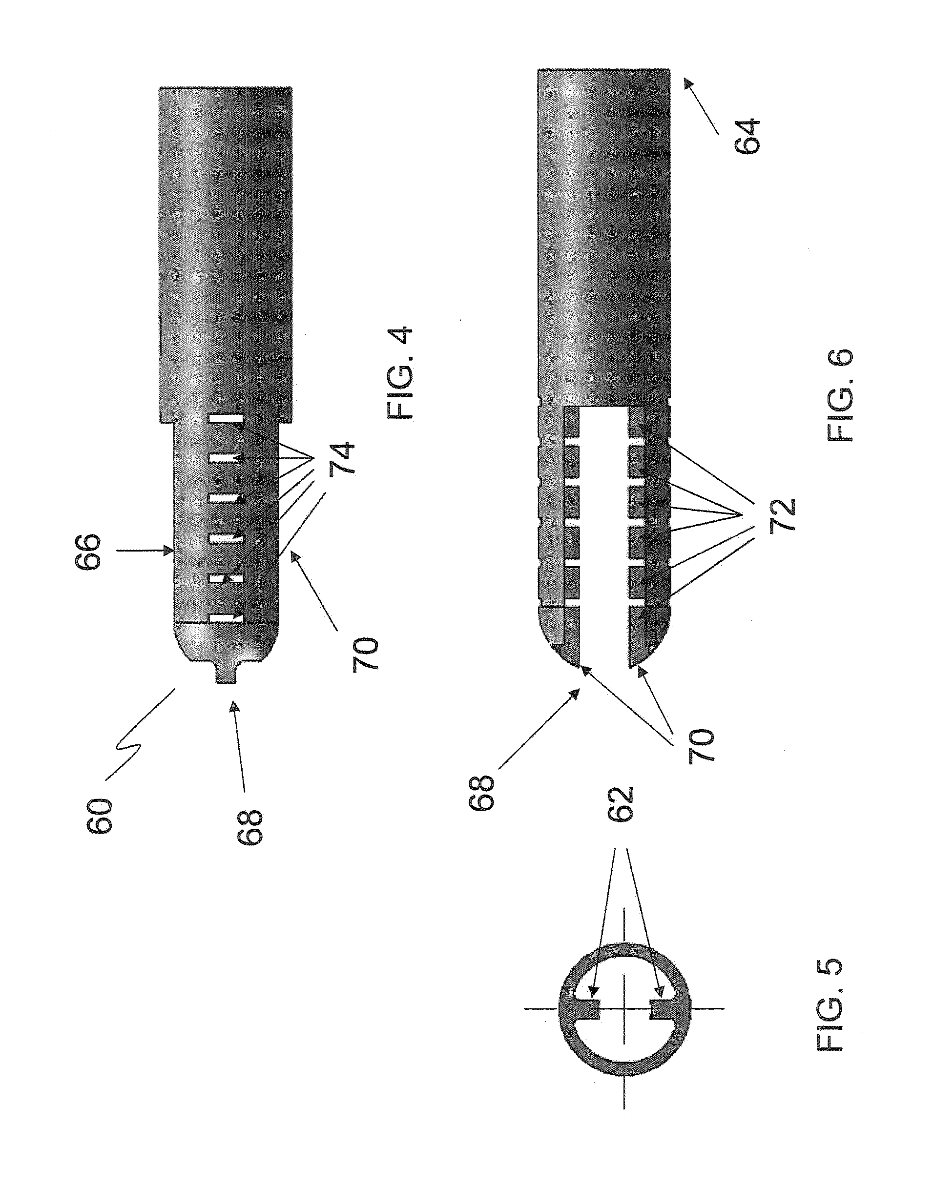
[0010]In one embodiment, the inner elongated shaft extends from the distal tip along the longitudinal axis of the outer cannula toward the proximal end of the cannula and includes a plurality of ridges or ribs extending radially from the shaft. The inner cannula rotatably disposed between the outer cannula and the inner shaft includes a cutting edge which interacts with the tissue cutting opening along with a plurality of blades which interact with the ridges or ribs of the inner shaft when the inner cannula is rotated. Such rotation facilitate cutting of the tissue and its maceration during aspiration to assist in its removal without clogging of the inner lumen.

Problems solved by technology

Two major disadvantages of such devices is their inability to (1) macerate or grind cut tissue that is drawn into the inner lumen of the device to an extent sufficient to avoid clogging of the lumen and allow aspiration of the tissue from the device, and (2) be used to treat more than one tissue type.
Many devices whose cutting tips are aggressive enough to remove bone are too aggressive to be used on cartilage without risk of damaging tissue around the treatment site.
Yet having a device which can be used with one such tissue but not the other requires deployment of multiple devices over the course of a procedure, adding to its length, cost and complexity.

Method used


Image

  • Surgical cutting device and method for performing surgery
  • Surgical cutting device and method for performing surgery
  • Surgical cutting device and method for performing surgery

Examples


Embodiment Construction

[0021]Referring now to the drawings, preferred embodiments of the present invention are shown in detail. Although the drawings represent embodiments of the present invention, the drawings are not necessarily to scale and certain features may be exaggerated to better illustrate and explain the present invention. The embodiments set forth herein are not intended to be exhaustive or otherwise limit the invention to the precise forms disclosed in the following detailed description.

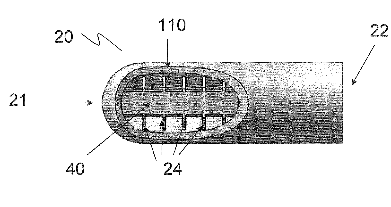
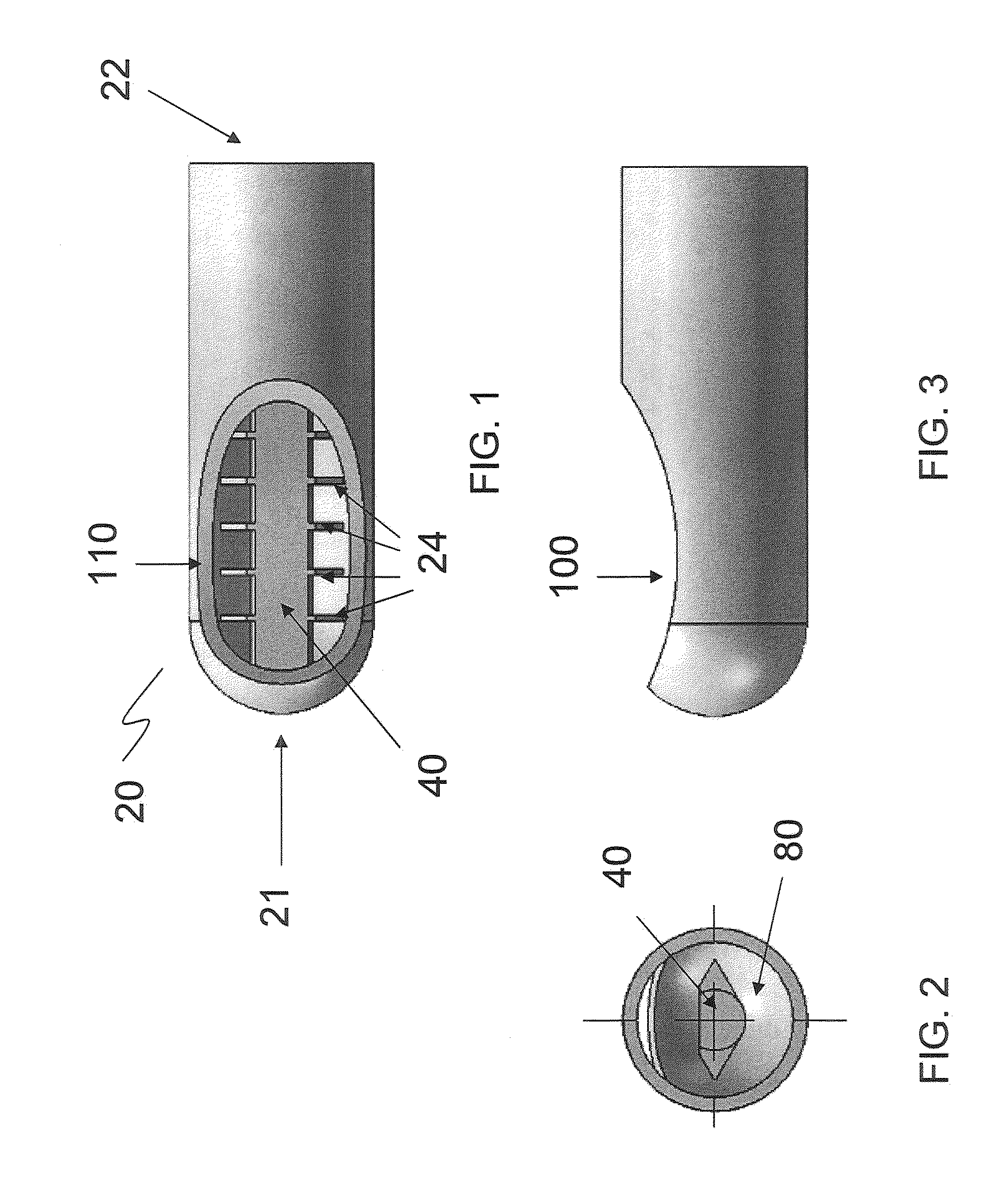
[0022]Referring to FIGS. 1-8, an embodiment of the distal cutting tip of a surgical cutting device 10 (FIG. 8) in accordance with the present invention is shown. The surgical cutting device includes a base (not shown), a catheter having at least one longitudinal lumen disposed between proximal and distal ends, an outer cannula 20 that is non-rotatably secured to or disposed within the distal end of the catheter, an inner elongated shaft 40 secured to the outer cannula 20 at its distal end 21, and an inner cann...


PUM


Abstract

A surgical cutting device and method for performing surgery using such is provided. The surgical device includes a handpiece or other, a stationary outer cannula connected to the base, a rotatable inner cannula connected to the base, an inner elongated shaft member connected to a distal interior surface of the lumen of the outer cannula, and a tissue cutting opening. The inner cannula includes a plurality of blades that interact with a plurality of ridges on the inner elongated shaft upon rotation of the inner cannula facilitating maceration of tissue within the lumen to prevent clogging of the device.

Description

CROSS REFERENCE TO RELATED APPLICATION(S)[0001]This application claims the benefit of priority under 35 U.S.C. §119(e) of U.S. Ser. No. 61 / 225,835, filed Jul. 15, 2009, the entire content of which is incorporated herein by reference.BACKGROUND OF THE INVENTION[0002]1. Field of the Invention[0003]The present disclosure relates generally to medical devices and more specifically to surgical cutting devices and methods for performing surgery using such devices.[0004]2. Background Information[0005]Many types of surgical procedures are routinely performed that require use of surgical cutting devices which enable removal of hard or soft tissue from the body. For example, arthroscopic surgery is a procedure, often minimally invasive, in which an examination of interior of a joint is performed using an arthroscope, with which a surgical device, such as an arthroscopic catheter, may be employed for treatment. Arthroscopic procedures can be performed either to evaluate or to treat many orthope...

Claims


Application Information

Patent Timeline
IPC IPC(8): A61B17/32
CPCA61B2017/320775A61B17/32002
Inventor SEIPEL, PETEHUNN, DAVID
Owner SEIPEL PETE
Learn More