

Control apparatus for hybrid vehicle
- Summary
- Abstract
- Description
- Claims
- Application Information
AI Technical Summary
Benefits of technology
Problems solved by technology
Method used
Image

Examples
embodiment 1
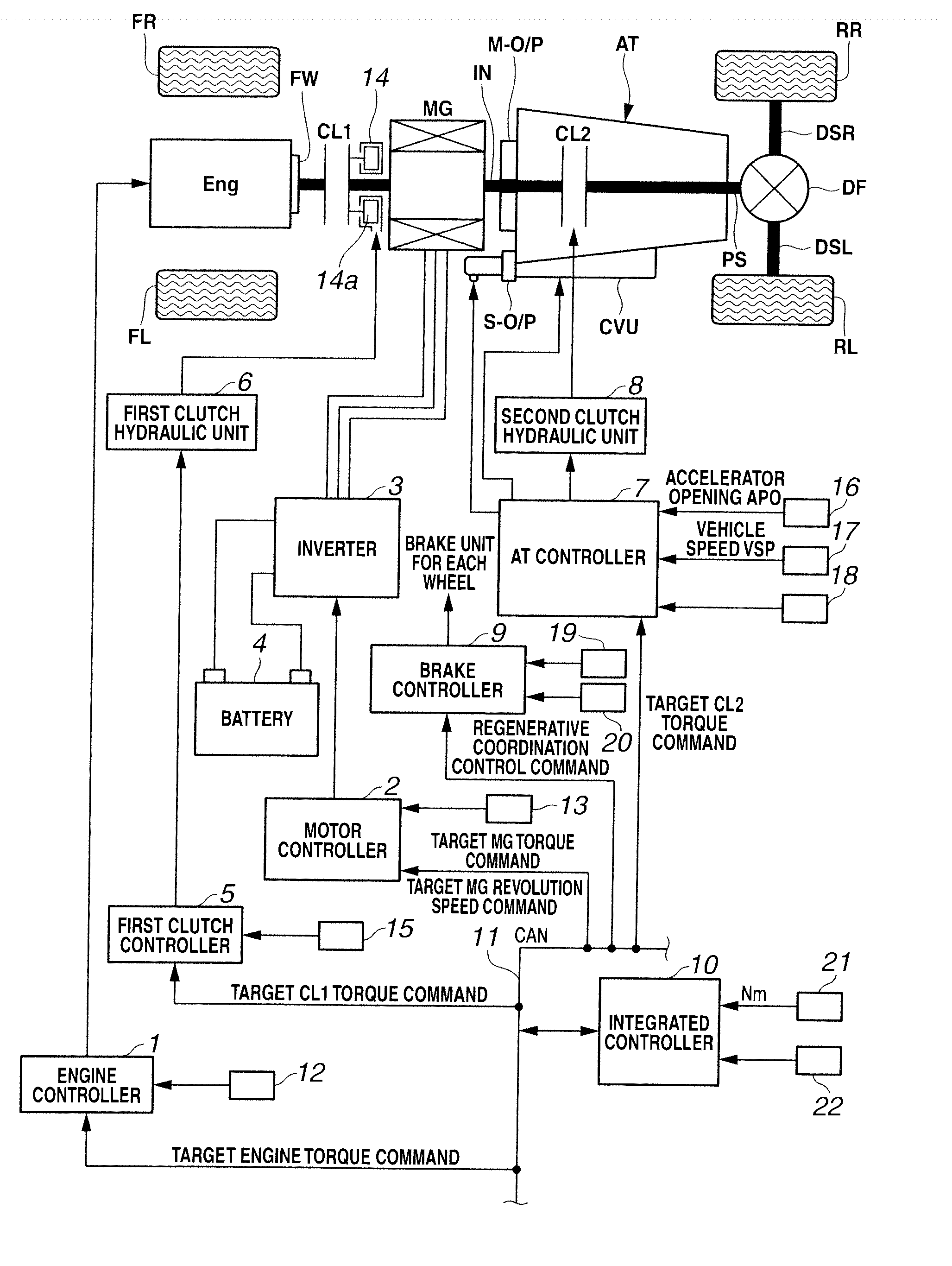
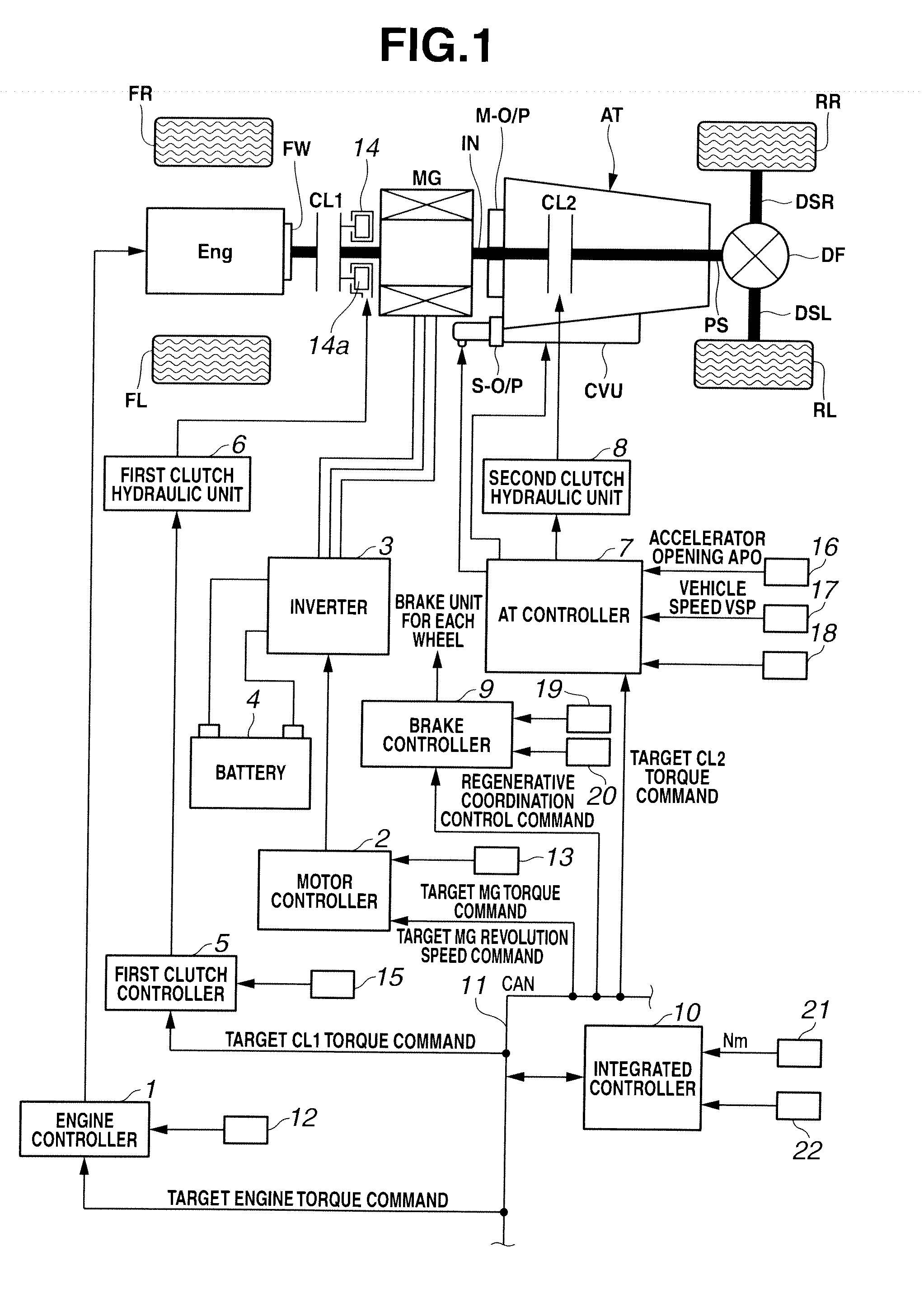
[0025]First, the whole system of the present invention will be explained. FIG. 1 is a system block diagram showing a rear-wheel-drive FR hybrid vehicle (an example of the hybrid vehicle) employing a control apparatus of an embodiment 1.
[0026]As can be seen in FIG. 1, a driveline of the FR hybrid vehicle in the embodiment 1 has an engine Eng, a flywheel FW, a first clutch CL1 (a first engagement element), a motor / generator MG (a motor), a second clutch CL2 (a second engagement element), an automatic transmission AT, a transmission input shaft IN, a mechanical oil pump M-O / P (a first oil pump), a sub-oil pump S-O / P (a second oil pump), a propeller shaft PS, a differential gear DF, a left drive shaft DSL, a right drive shaft DSR, a rear-left wheel (driving wheel) RL, and a rear-right wheel (driving wheel) RR. FL is a front-left wheel, FR is a front-right wheel.
[0027]The engine Eng is a gasoline engine or a diesel engine, and the flywheel FW is provided on an engine output shaft. On the...
PUM
 Abstract
Description
Claims
Application Information