Mole Trap

a technology of mole traps and mounds, which is applied in the field of mole traps, can solve the problems of unsightly mounds and upward disturbance of the earth, and achieve the effects of less intimidating use, easy setting and release, and less intimidating us

Active Publication Date: 2011-04-21
OMS INVESTMENTS INC
View PDF13 Cites 7 Cited by
  • Summary
  • Abstract
  • Description
  • Claims
  • Application Information

AI Technical Summary

Benefits of technology

[0007]The mole trap of the present invention is formed primarily of plastic components and is readily set and released without the use of the user's hands, and is thereby more approachable and less intimidating to use. The base has two spaced pointed fixed blades. Each fixed blade has a pivoting blade mounted in close proximity in a scissors arrangement. A catch is pivotably mounted about a first axis at a first end to the base. A lever has a first segment which is pivotably connected to a second segment. The first lever segment is pivotably mounted about a second axis to the base, and the second lever segment is pivotably connected to the pivoting blades. Two springs extend between the second lever segment and the base to urge the pivoting blades to close with the fixed blades. The catch has an upwardly projecting

Problems solved by technology

Formation of these runways thus results in the earth being disturbed upwardly which forms unsightly mounds.
Yet these mec

Method used


Image

  • Mole Trap
  • Mole Trap
  • Mole Trap

Examples


Embodiment Construction

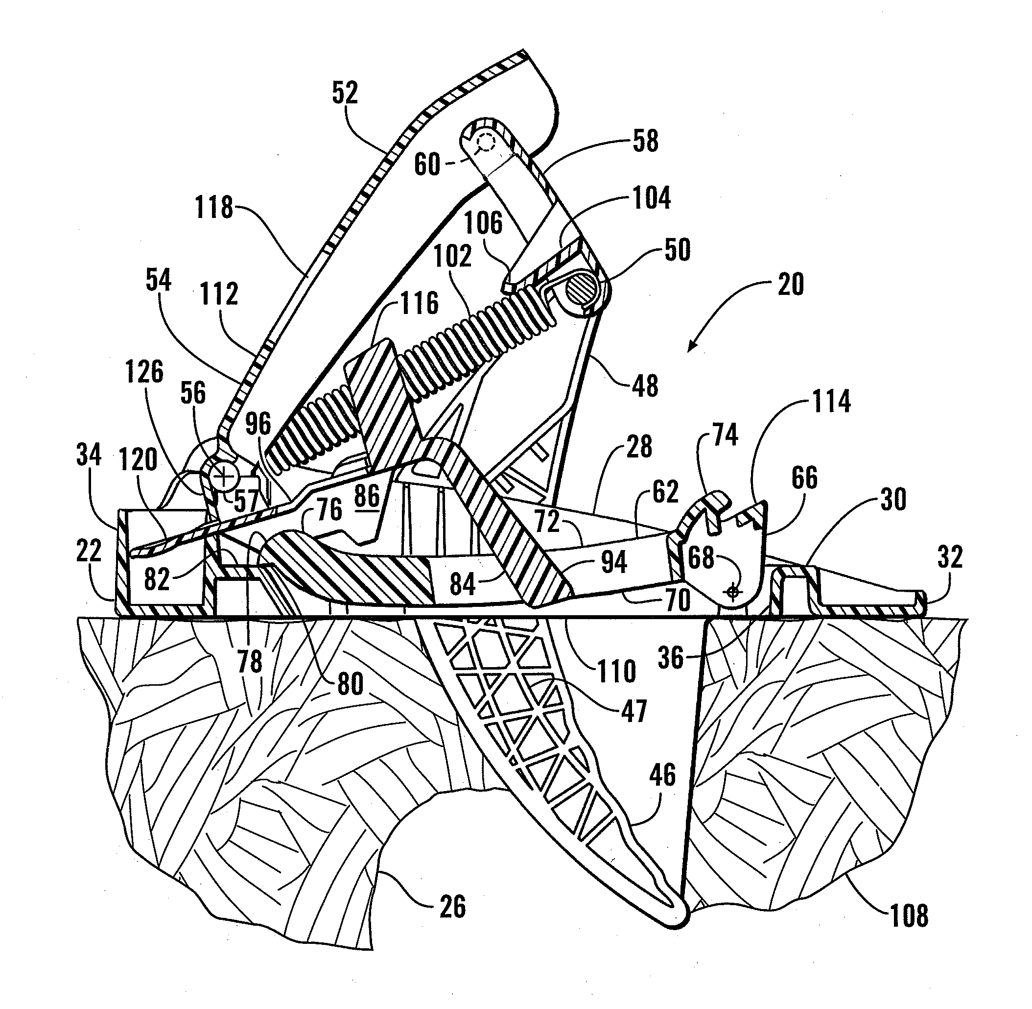
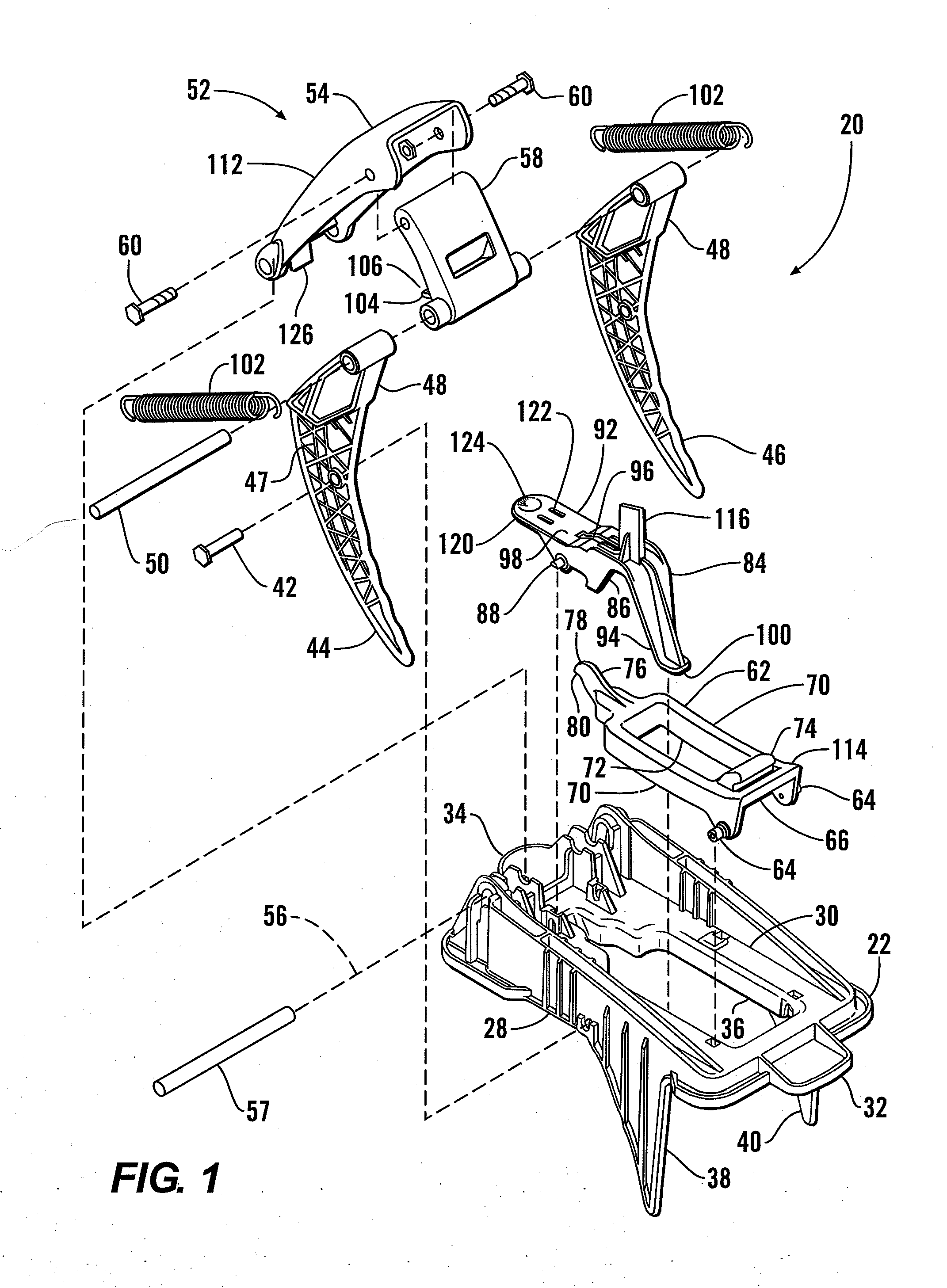
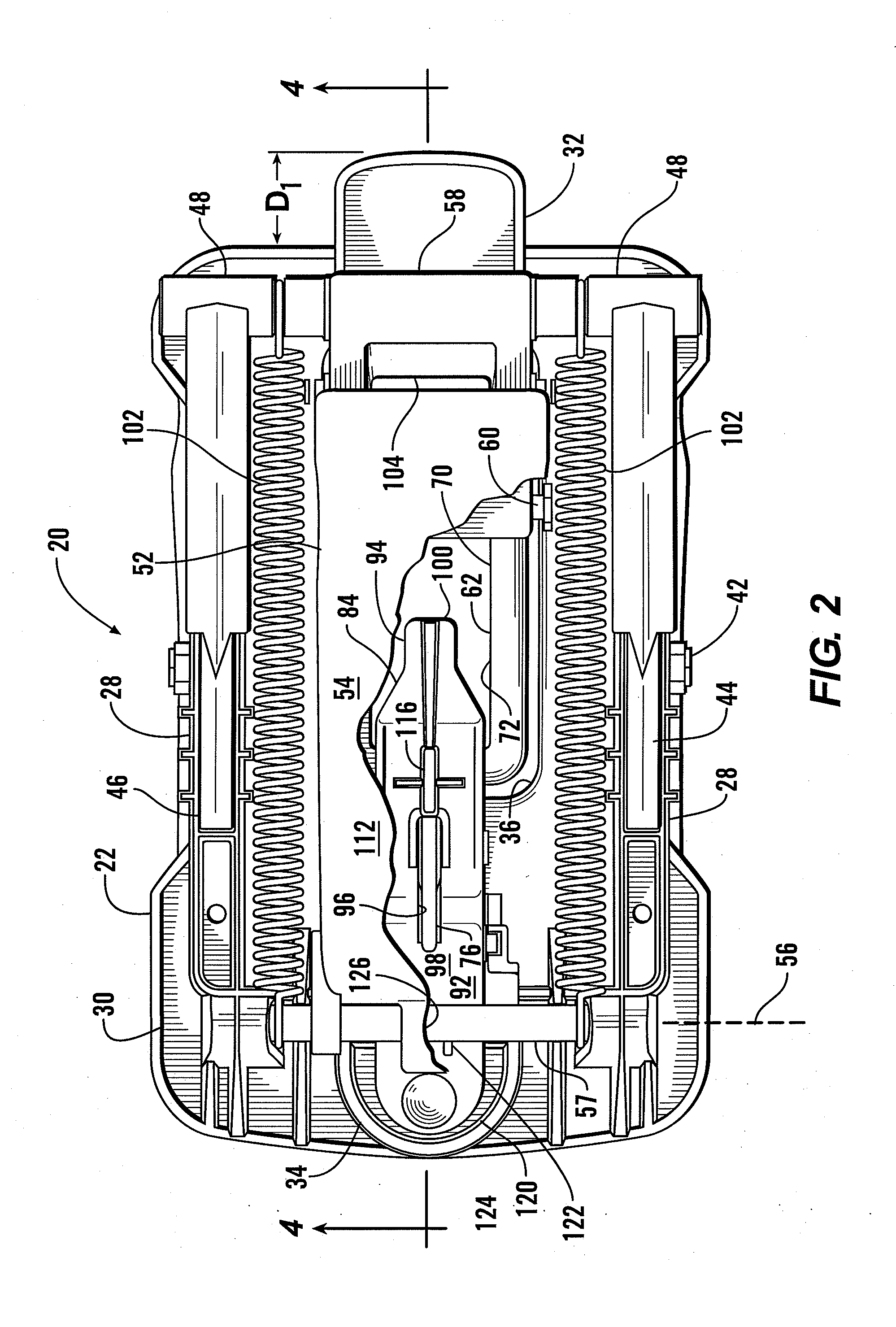
[0017]Referring more particularly to FIGS. 1-4, wherein like numbers refer to similar parts, a mole trap 20 is shown. The trap 20 has a plastic base 22 which has a platform 30 configured to be disposed at ground level overlying an underground pest runway 26, such as shown in FIGS. 3 and 4. The base 22 has two side walls 28 which extend upwardly from the horizontal platform 30. A depth gauge 32 protrudes frontwardly from the platform 30, and a release tab shroud 34 extends rearwardly from the platform. A central opening 36 is defined within the platform 30 between the two side walls 28.

[0018]A roughly triangular first fixed blade 38 extends downwardly from the base platform 30, so that the blade may be inserted in the soil into or adjacent to the pest runway 26. The first fixed blade 38 may be substantially aligned with one of the side walls 28. A second fixed blade 40 is similar to the first fixed blade 38 and is positioned parallel to it and extending downwardly from the other of t...


PUM


Abstract

A mole trap has a tough plastic base with downwardly extending fixed blades. Movable plastic blades are pivotably connected to the base and urged into a sprung condition by springs. A two-segment lever extends between the base and a catch which is pivotably mounted to the base. A trigger extends through a central opening in the catch and has a post which protrudes beneath the catch where it can be actuated by the targeted mole. Operation of the trigger post causes the lever to release from its engagement with the catch so that the movable blades close on and strike the mole positioned beneath the trap. The trigger has a release tab extending from the lever, allowing convenient release from the set position, and an upwardly protruding set arm allowing trigger depression from a point exterior to the handle into its desired set configuration.

Description

CROSS REFERENCES TO RELATED APPLICATIONS[0001]Not applicable.STATEMENT AS TO RIGHTS TO INVENTIONS MADE UNDER FEDERALLY SPONSORED RESEARCH AND DEVELOPMENT[0002]Not applicable.BACKGROUND OF THE INVENTION[0003]The present invention relates to animal traps in general, and more particularly to devices for entrapping moles.[0004]Subterranean mammals such as the mole spend most of their time underground traversing a network of narrow diameter runways. Although some of these passageways are more distant from the surface, many are closely positioned beneath ground level. Formation of these runways thus results in the earth being disturbed upwardly which forms unsightly mounds. These pests are seldom seen aboveground, and thus control of moles requires bringing countermeasures to their subterranean domain.[0005]Although various poisons and repellants may be employed, these bring with them the requirement to secure the substances against children, pets, and non-targeted species. An alternative...

Claims


Application Information

Patent Timeline
IPC IPC(8): A01M17/00A01M23/26
CPCA01M27/00A01M23/36
Inventor WALSH, JAMES R.ZEAMER, PAUL R.JOHNSON, DANIEL C.
Owner OMS INVESTMENTS INC
Why Eureka
Try Eureka