Rotation-rate sensor having two sensitive axes
- Summary
- Abstract
- Description
- Claims
- Application Information
AI Technical Summary
Benefits of technology
Problems solved by technology
Method used
Image
Examples
Embodiment Construction
[0017]Exemplary embodiments of the present invention are shown by way of example in the Figures and are described below.
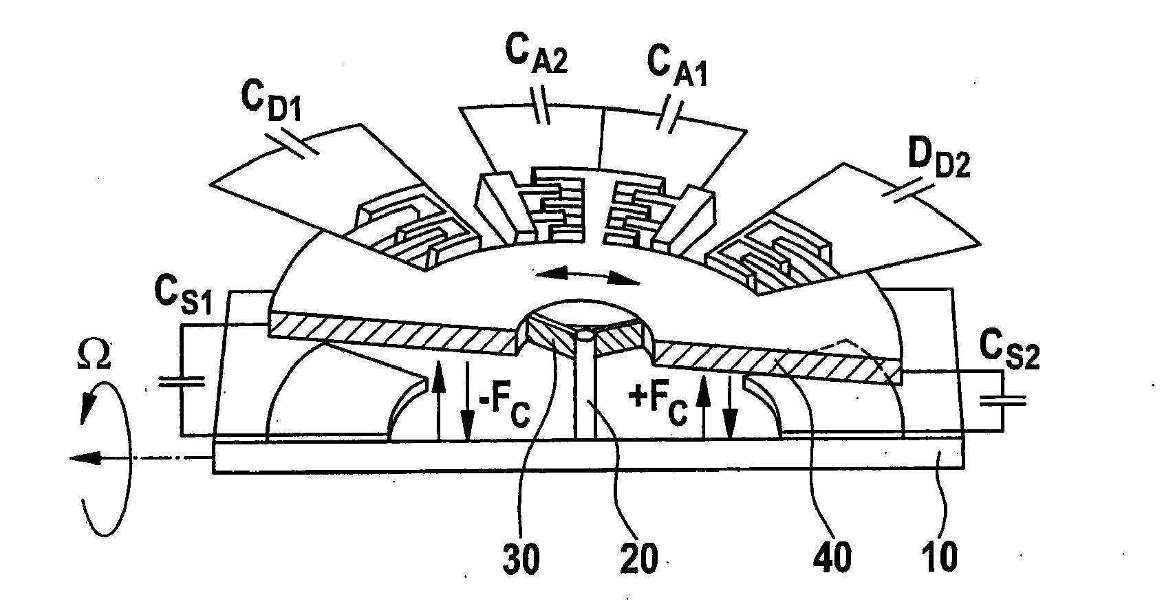
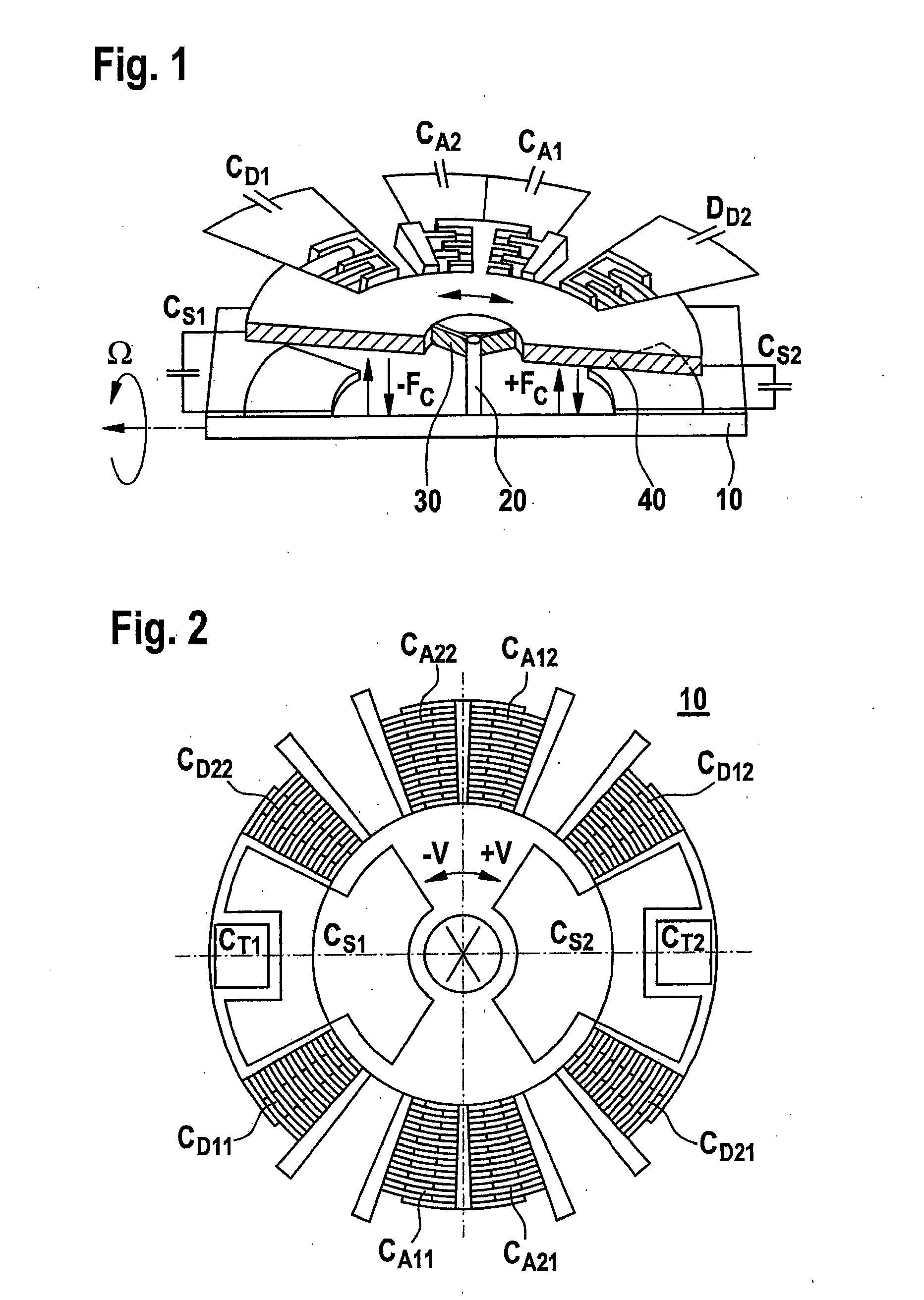
[0018]FIG. 1 shows the micromechanical functional part of a rotation-rate sensor according to the related art. The rotation-rate sensor is shown in a schematic sectional view. The figure shows a substrate or support 10, a hub 20 having suspension springs or vibrating springs 30 and a vibrating mass 40. Hub 20 is connected to support 10. Via vibrating springs 30, the hub is also connected to vibrating mass 40. The rotation-rate sensor has drive means in the form of comb structures CA1, CA2, which drive vibration V. The seismic mass or vibrating mass 40 capable of being excited to vibrate is driven by the fact that the two combs of a drive structure such as CA1, for example, represent two electrodes that are charged to different electrical potentials. The complementary combs are drawn into each other as a result of the electrostatic force of attraction, and vibrating...
PUM
 Abstract
Description
Claims
Application Information
 - R&D
- Intellectual Property
- Life Sciences
- Materials
- Tech Scout
- Unparalleled Data Quality
- Higher Quality Content
- 60% Fewer Hallucinations
Browse by: Latest US Patents, China's latest patents, Technical Efficacy Thesaurus, Application Domain, Technology Topic, Popular Technical Reports.
© 2025 PatSnap. All rights reserved.Legal|Privacy policy|Modern Slavery Act Transparency Statement|Sitemap|About US| Contact US: help@patsnap.com


