
Water-cooled Cooling Apparatus Integrated to Load Devices

Inactive Publication Date: 2015-10-22
MISSION CRITICAL SOLUTIONS
View PDF9 Cites 5 Cited by
  • Summary
  • Abstract
  • Description
  • Claims
  • Application Information

AI Technical Summary

Benefits of technology

The present invention provides a water-cooled cooling apparatus integrated to load devices that can protect electronic devices from overheating when a utility power outage happens or any specific numbers of electrical fan failure. The apparatus has a high efficiency and high reliability. The cooling surfaces formed by cooling coils of the water-cooled cooling device are very close to the cabinet group so that the hot airflow can be immediately transferred from the cabinet group to the cooling coils, through the enclosed airflow space, then through electrical fans and back to the common cold airflow chamber, which reduces the power requirement for the electrical fans. The mounting installation for the apparatus is modular, scalable and flexible to fit into any open warehouse space with ease. The apparatus can be built independently from another or ship assembled for plug and play in place, achieving more customized options with similar economic form factor.

Problems solved by technology

From airflow perspective, the open configuration may not provide proactive air management to the rack cabinets either.
Besides low effectiveness on energy usage and air management, the fans of the cooling equipment may not be supported by Uninterruptible Power Supply (UPS) system.
In a power interruption event, the facility room cooling effectiveness is further compromised.
It is also an intriguing challenge to provide a highly efficient cooling apparatus for an electronic facility room with effective and reliable UPS solution for cooling the electronic load devices.

Method used


Image

  • Water-cooled Cooling Apparatus Integrated to Load Devices
  • Water-cooled Cooling Apparatus Integrated to Load Devices
  • Water-cooled Cooling Apparatus Integrated to Load Devices

Examples


first embodiment

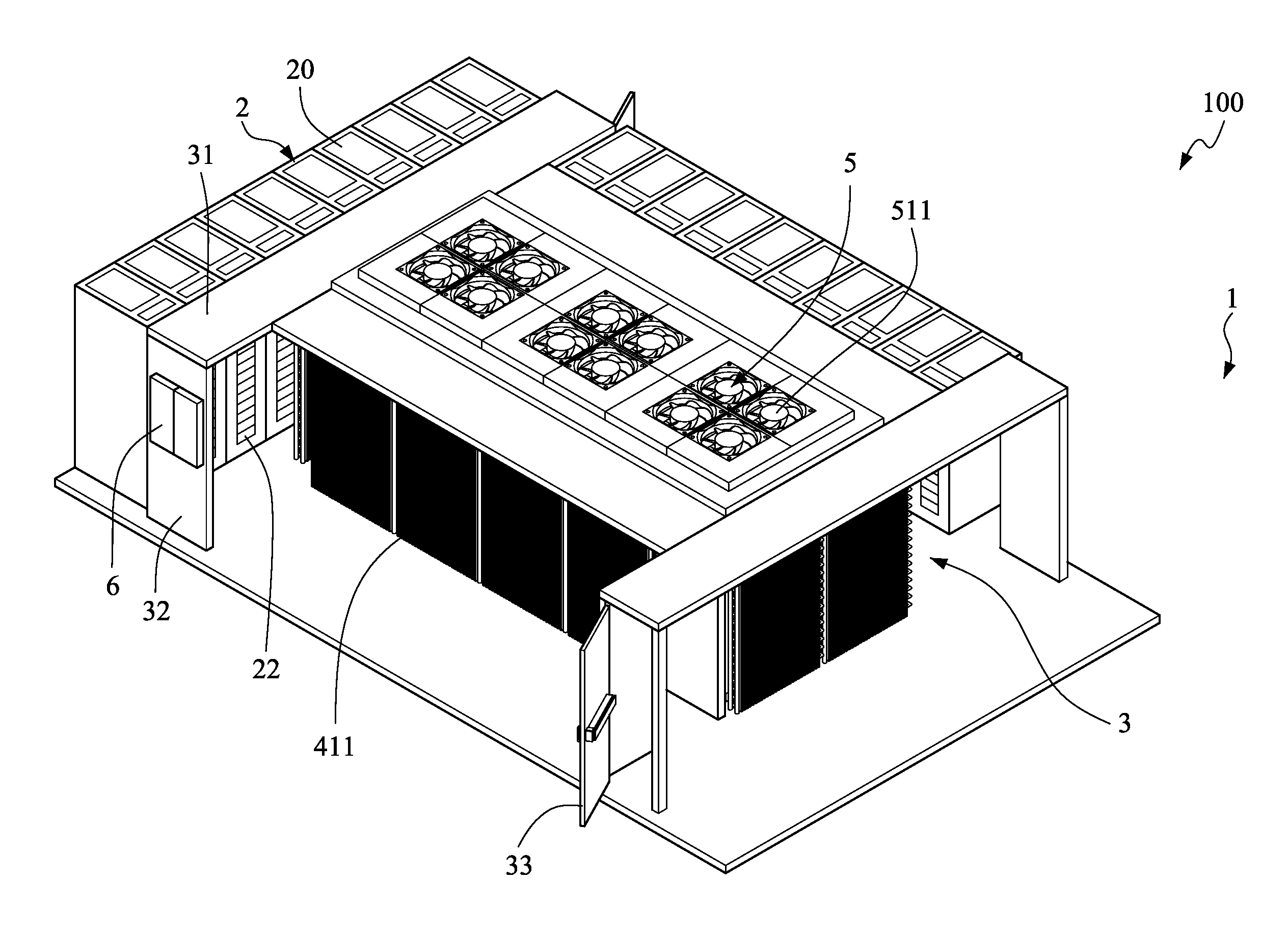
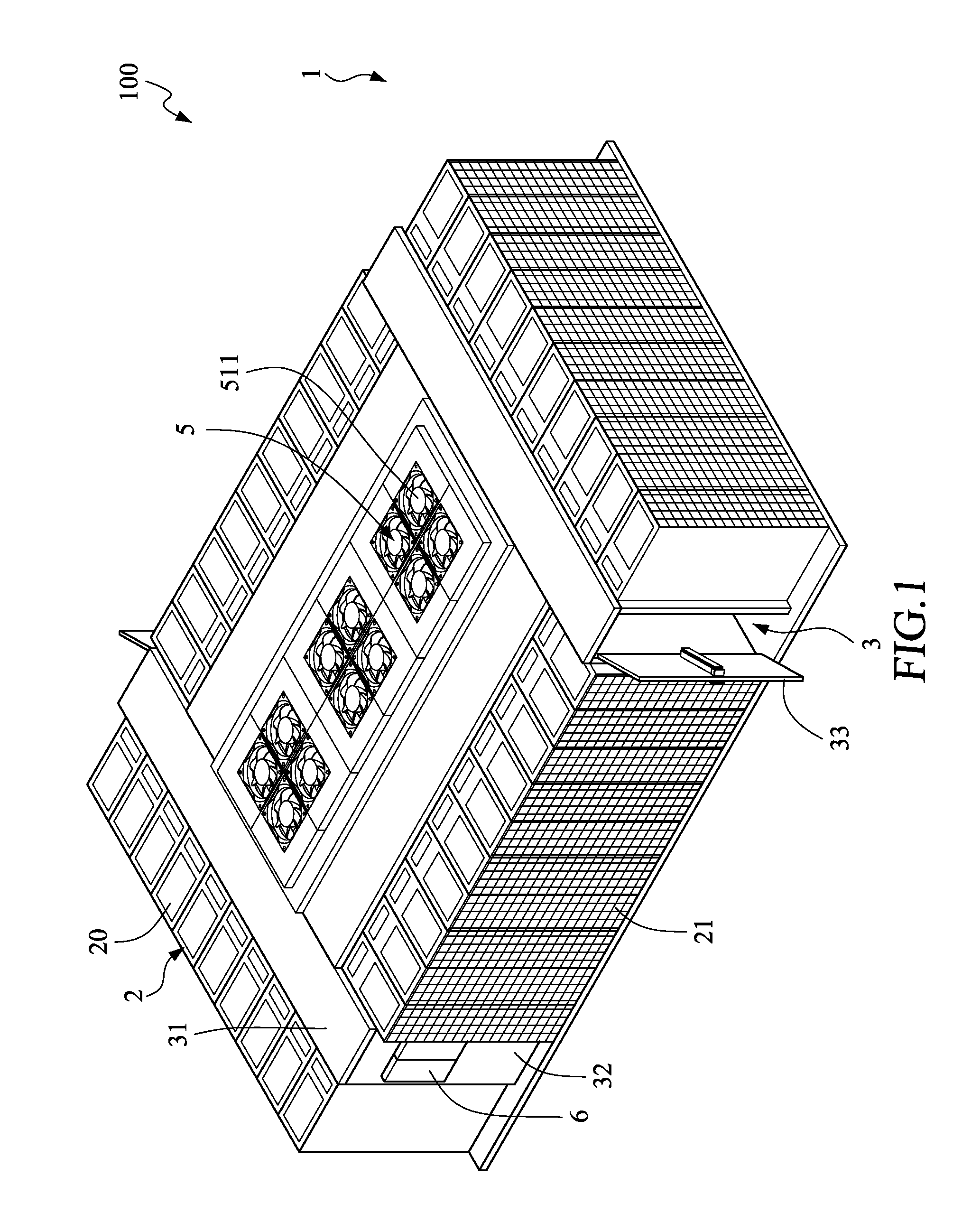
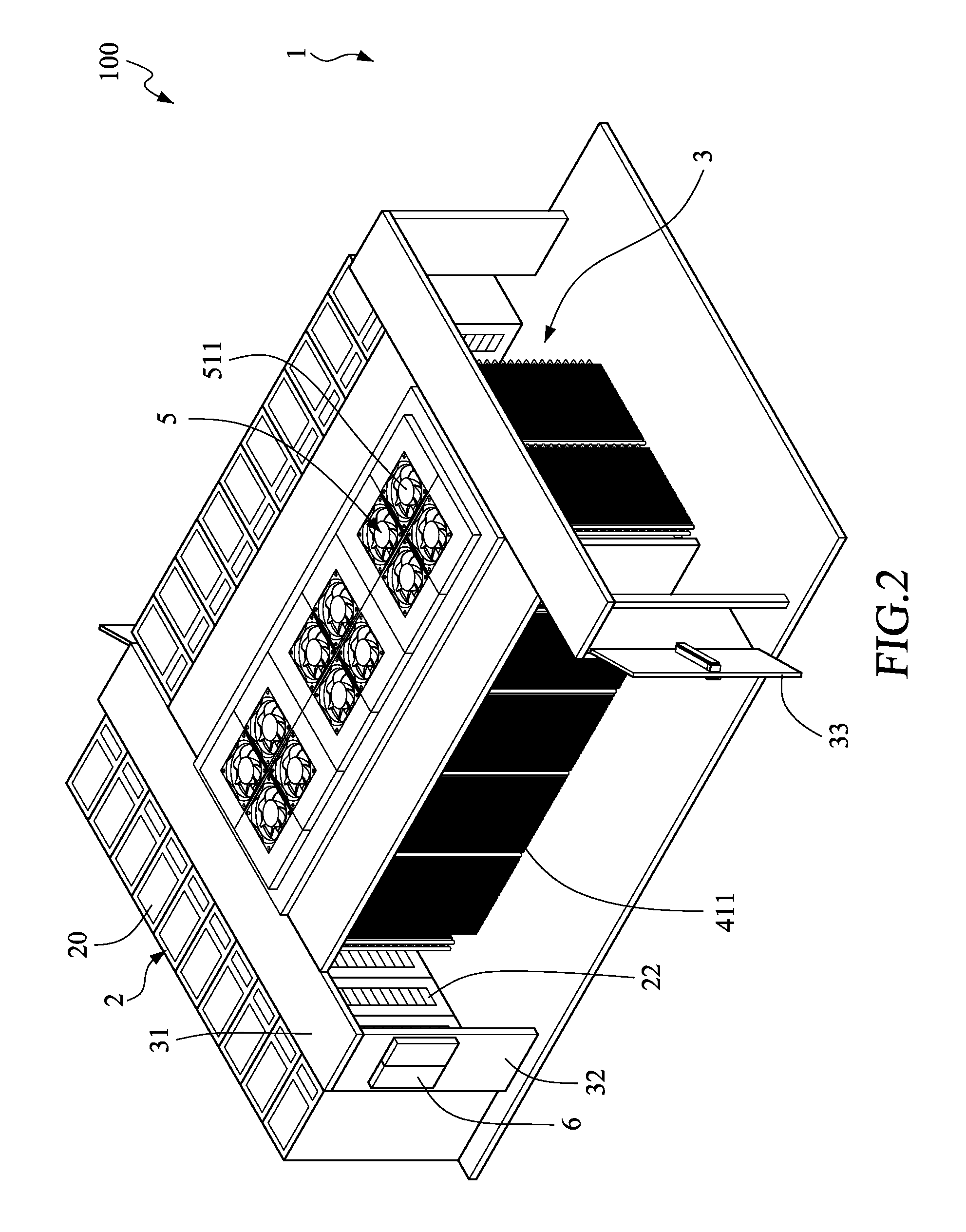
[0024]Refer to FIG. 1 to FIG. 4. A water-cooled cooling apparatus integrated to load devices 100 includes a common cold airflow chamber 1, multiple cabinet groups 2, a common warm airflow tunnel 3, a water-cooled cooling device 4, a group of electrical fans 5, and a power switchboard and / or control panel device 6, according to the present invention.

[0025]The common cold airflow chamber 1 surrounds around the multiple cabinet groups 2 and is for providing cold air that is for air cooling. In the embodiment, the common cold airflow chamber 1 is provided with cold air which is cooled by the water-cooled cooling apparatus integrated to load devices 100.

[0026]In the embodiment, the water-cooled cooling apparatus integrated to load devices 100 is provided with four cabinet groups 2, and the four cabinet groups 2 are formed and arranged as a rectangle shape. The common cold airflow chamber 1 surrounds around the outside of the four cabinet groups 2, and the common warm airflow tunnel 3 is ...

second embodiment

[0032]By means of the present invention with UPS, redundant power distribution and redundant fans, the group of electrical fans 5 can supply continuous airflow to prevent the risk of airflow stopping when utility power is not stable, or temporarily power interruptions, or any specific electrical fans are out of order. Accordingly, the load devices 23 of the cabinet groups 2 will not being overheated because of loss of airflow. Further, the water-cooled cooling device 4 or the cooling operation uses water, which has greatest specific heat, as cooling media. Therefore, the water cooled cooling device 4 can effectively process heat exchange with lowest energy requirement. Furthermore, the cooling surfaces formed by the cooling coils 41 of the water-cooled cooling device 4 is closely located to the cabinet groups 2, so that the hot air from the cabinet groups 2 is able to be immediately transfer through the cooling coil 41 to the enclose airflow space S, then through the group of electr...


PUM


Abstract

Disclosed is a water-cooled cooling apparatus integrated to load devices comprising: a common cold airflow chamber, a common warm airflow tunnel, a cabinet group, a water-cooled cooling device, and a group of electrical fans, wherein the enclosed airflow space is surrounded by the water-cooled cooling device and the group of electrical fans. Accordingly, a high efficiency and continuous cooling effect is provided.

Description

FIELD OF THE INVENTION[0001]The present invention relates to a cooling apparatus for a composite electronic facility room, and more particularly to a water-cooled cooling apparatus integrated to load devices.BACKGROUND OF THE INVENTION[0002]In a conventional arrangement, electronic devices are housed in a facility room such as, but not limited to, computer room, server room, colocation room, switch room, etc. Part of functions of the facility room is to cool operational electronic devices. Normally there are air moving equipment galleries next to the facility room. These galleries may be a part of open facility room or they may be partitioned as separate rooms. These galleries house the cooling equipment that delivers cold airflow to the facility room. Normally the facility room is an open space. This open space maybe arranged to have open cold aisle way and open hot aisle way. Usually standard rack cabinets are placed in this open space or placed between open cold and hot aisle way...

Claims


Application Information

Patent Timeline
IPC IPC(8): H05K7/20G06F1/20
CPCH05K7/20172H05K7/20218G06F1/20H05K7/2079H05K7/20745G06F2200/201
Inventor SAITA, MARCOSUN, SHIHWEI
Owner MISSION CRITICAL SOLUTIONS
Learn More