
Vehicle engine

A technology of engine and heat engine, applied in the direction of engine components, machines/engines, vehicle energy storage, etc., to achieve the effect of assisting in small energy demand and low nitrogen and sulfur pollution

Inactive Publication Date: 2009-10-07
马丁拉森
View PDF3 Cites 0 Cited by
  • Summary
  • Abstract
  • Description
  • Claims
  • Application Information

AI Technical Summary

Problems solved by technology

[0010] None of the above documents deal with the hybrid engine driving the vehicle

Method used


Image

  • Vehicle engine
  • Vehicle engine
  • Vehicle engine

Examples


Embodiment Construction

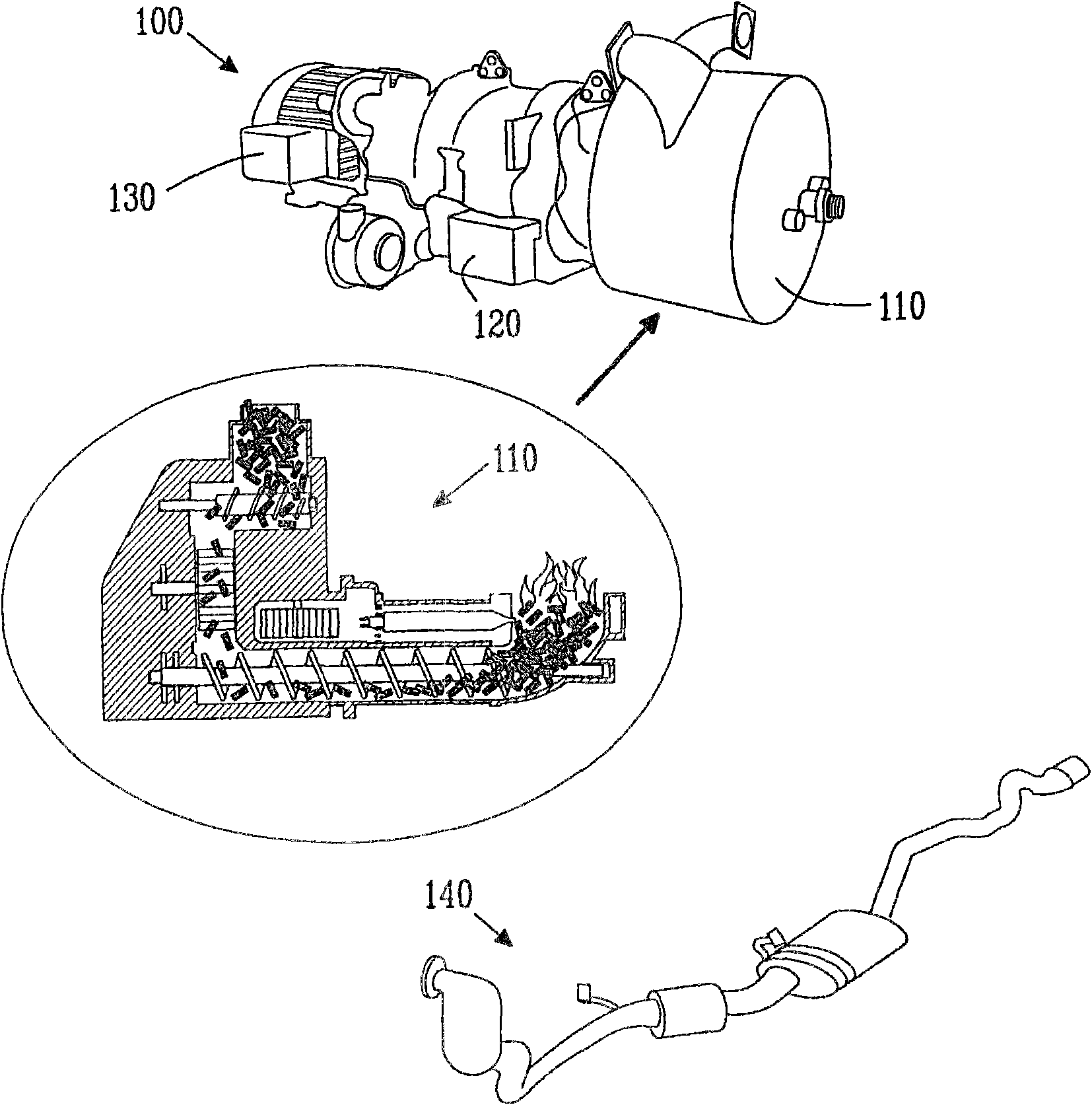
[0027] figure 1 A specific device according to the invention illustrates various parts of the engine. The present engine 100 consists of an external heating system 100 cooperating with a heat engine 120 connected to a generator 130 .

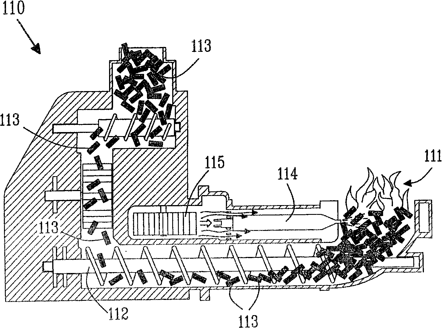
[0028] According to one embodiment of the present invention, the external heating system includes a pellet combustion or combustion heating device 110 . According to this example, if figure 2 As shown, the particle combustion heating device includes: a combustion chamber with a combustion zone 111; a transport device for providing fuel particles 113 in the combustion zone; a burner 114 for controlling fuel combustion in the combustion zone; a pressure to provide air to the combustion zone regulator (or fan) 115; an exhaust system (not shown) for removing combustion gases from the combustion chamber; and optionally a fan (not shown) for directing air through the exhaust system into the heated space.

[0029] Obviously, other types of pellet c...


PUM


Abstract

The present invention relates to A vehicle engine (100) comprising a combustion part (110), a heat engine (120) and an electrical generator (130). The combustion part (110) comprises a pellet burning unit, which is arranged to generate heat by burning pellets, said pellet burning unit is connected to said heat engine (120), which heat engine is arranged to convert heat from said pellet burning unit to kinetic energy, said electrical generator is arranged to convert said kinetic energy from said heat engine to generate electrical energy for actuating wheels of said vehicle.

Description

technical field [0001] The present invention relates to an enhanced vehicle engine system, and more particularly to vehicle engines utilizing particulate or similar energy sources. Background technique [0002] The high cost of fossil fuels and environmental requirements force new and innovative alternatives to internal combustion engines. [0003] Automobile manufacturers invest significant resources in developing new environmentally friendly engines. More and more hybrid engines are being developed and vehicles equipped with such hybrid engines are being sold. Almost all hybrid engines still require gasoline or diesel as the sole fuel source, although others such as ethanol or vegetable oils are occasionally used. Many other hybrid vehicles use hydrogen fuel. [0004] Wood pellet fuel is a type of wood fuel, usually made from compacted sawdust. They are usually by-products of sawmilling or other wood-deformation conversion activities. These particles are extremely den...

Claims


Application Information

Patent Timeline
Patent Type & Authority Applications(China)
IPC IPC(8): F02G1/043F23K3/14B60L50/10
CPCF23G2205/121B60L7/14Y02T10/70F23G7/105F23K3/14B60L11/123F23B40/04B60L11/14F23G2209/261Y02T10/6217Y02T10/7077Y02E20/12F23G5/40F23G2206/203F02G2254/11F23G2203/601B60L50/16B60L50/61Y02T10/62Y02T10/7072F02G1/043
Inventor 马丁·拉森
Owner 马丁拉森
Learn More