

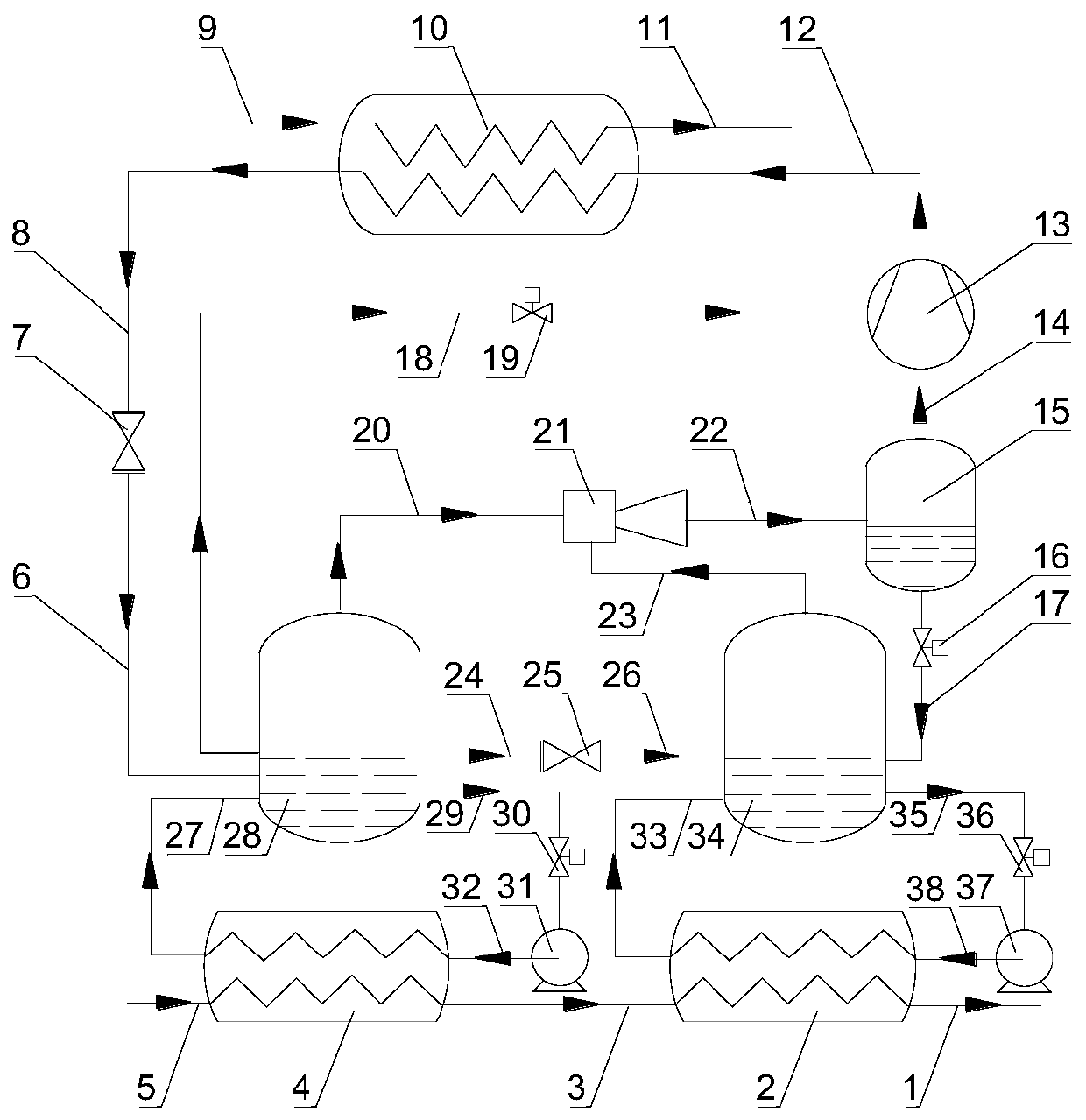
Water working medium injection type heat pump system realizing cascaded recovery of waste heat and working method thereof
A jet heat pump and waste heat recovery technology, applied in heat recovery systems, heat pumps, machines that use waste heat, etc., can solve the problem of narrowing the temperature range of waste heat recovered by hydraulic heat pumps, reducing the amount of waste heat recovered by hydraulic heat pumps, and reducing water consumption. The economy and practicability of the working fluid heat pump are solved to achieve the effect of expanding the available temperature range, ensuring normal and stable operation, and avoiding low work efficiency.
- Summary
- Abstract
- Description
- Claims
- Application Information
AI Technical Summary
Problems solved by technology
Method used
Image

Examples
Embodiment Construction
[0042] The present invention will be described in detail below in conjunction with specific embodiments. The following examples will help those skilled in the art to further understand the present invention, but do not limit the present invention in any form. It should be noted that those skilled in the art can make several changes and improvements without departing from the concept of the present invention. These all belong to the protection scope of the present invention.
[0043] A preferred example of the present invention provides a cascaded waste heat recovery water jet heat pump system. This system can not only use natural working fluid water as the working medium of the heat pump system, but also realize cascade recovery and utilization of waste heat resources, effectively reducing the The available temperature of waste heat resources is increased, the temperature range of effective use of waste heat resources is expanded, the waste heat that can be recovered by the h...
PUM
 Abstract
Description
Claims
Application Information