
System and method for producing low-temperature water through microporous flash evaporation

A microporous and flash evaporation technology, applied in refrigerators, refrigeration components, refrigeration and liquefaction, etc., can solve the problems of high investment, limited promotion and application of water refrigerant refrigeration systems, etc.

Active Publication Date: 2020-10-23
天津乐科节能科技有限公司 +1
View PDF8 Cites 2 Cited by
  • Summary
  • Abstract
  • Description
  • Claims
  • Application Information

AI Technical Summary

Problems solved by technology

Patent CN106705308A discloses a mechanical flash-type air-conditioning and refrigeration system, which uses water as a refrigerant to produce low-temperature cold water for air-conditioning through mechanical flashing. The system has good thermal cycle performance, but due to the ratio of water vapor Large volume, for example, the specific volume of saturated water vapor at 7°C is 129m 3 / kg, while the steam specific volume of R134a under the same temperature conditions is 0.054m 3 / kg, the steam specific volume of R407C is 0.042m 3 / kg, it can be seen that the specific volume of water vapor is much larger than the gas specific volume of freon refrigerants at the same temperature, which leads to the need for a steam compressor with a large flow rate in the water refrigerant system, and the high investment in system equipment limits the water refrigerant to a certain extent Popularization and Application of Refrigeration System

Method used


Image

  • System and method for producing low-temperature water through microporous flash evaporation
  • System and method for producing low-temperature water through microporous flash evaporation
  • System and method for producing low-temperature water through microporous flash evaporation

Examples


Embodiment 1

[0020] The present invention will be described in further detail below in conjunction with the accompanying drawings and specific embodiments, and the given examples are only used to explain the present invention, and are not intended to limit the scope of the present invention.

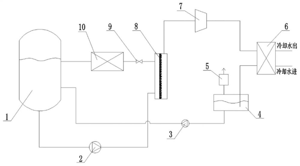
[0021] figure 1 It is the schematic diagram of the system of this embodiment; a system for microporous flash evaporation to produce low-temperature water, consisting of a water tank 1, a booster pump 2, a return pump 3, a condensate tank 4, a vacuum pump 5, a condenser 6, and a compressor 7 , a microporous hydrophobic material assembly 8, a pressure reducing valve 9, and a cooler 10.

[0022] The bottom of the water tank 1 is provided with a circulating water outlet, and the side wall is provided with a circulating water return port and a condensate return port; the inside of the microporous hydrophobic material component 8 is a microporous hydrophobic material, and one side of the microporous hydrop...


PUM


Abstract

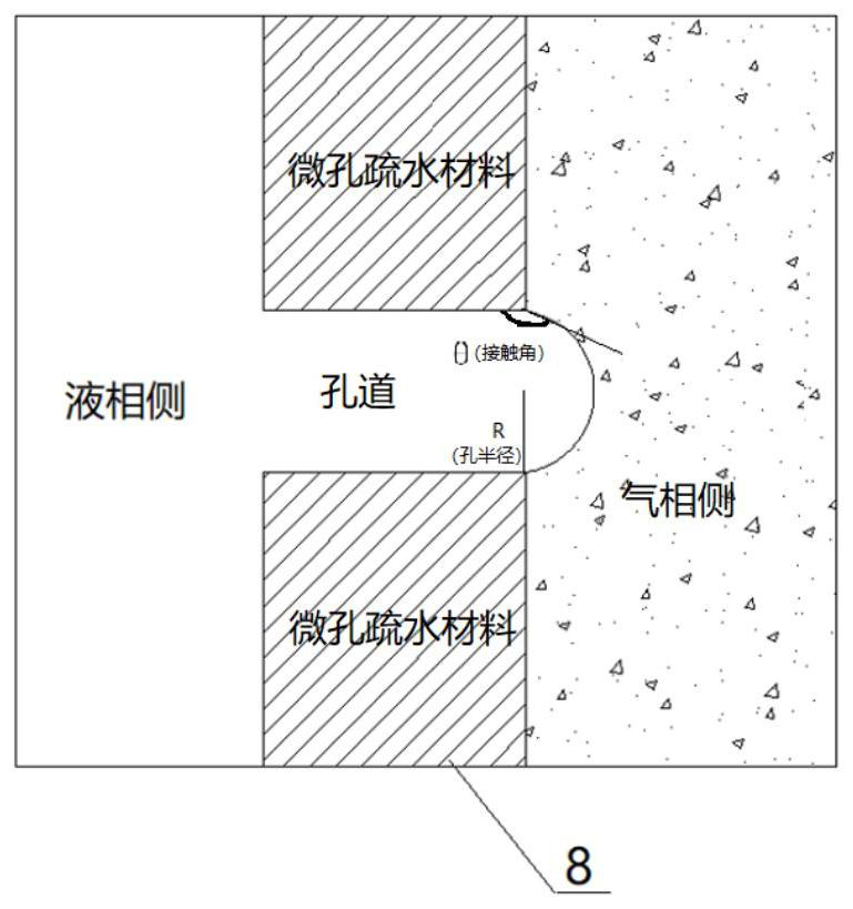
The invention discloses a system and method for producing low-temperature water through microporous flash evaporation. The system comprises a water tank, a booster pump, a reflux pump, a condensate tank, a vacuum pump, a condenser, a compressor, a microporous hydrophobic material assembly, a reducing valve and a cold dissipation device. The system is based on the Laplace law, and in other words, the saturated vapor pressure on the surfaces of convex liquid drops is higher than that of plane liquid drops; water is pressurized to penetrate the microporous hydrophobic material assembly, and then,the convex liquid drops are formed; and the flash evaporation pressure formed when water flash evaporation occurs is increased, and the compression ratio of the compressor is reduced. According to the system and method, the water serves as a refrigerant, and the system achieves the remarkable environment protection feature; the convex liquid drops are obtained through the microporous hydrophobicmaterial assembly, and the saturation pressure and specific volume formed when water flash evaporation occurs are changed; and operation energy consumption of the system can be remarkably lowered, andthe size of compressor equipment can be remarkably reduced. The system for producing the low-temperature water through microporous flash evaporation has the beneficial effects of energy conservation,environmental protection and the like.

Description

technical field [0001] The invention relates to a system for producing low-temperature water, in particular to a system and method for producing low-temperature water through microporous flash evaporation technology, and belongs to the technical field of refrigeration. Background technique [0002] At present, most of the refrigerants in the refrigeration field use freon refrigerants, which have poor environmental performance and have more or less ozone layer destruction or greenhouse gas effects. As a natural working fluid, water (refrigerant code: R718) has significant advantages in terms of system cost, safety, environmental protection and thermal performance. Patent CN106705308A discloses a mechanical flash-type air-conditioning and refrigeration system, which uses water as a refrigerant to produce low-temperature cold water for air-conditioning through mechanical flashing. The system has good thermal cycle performance, but due to the ratio of water vapor Large volume, ...

Claims


Application Information

Patent Timeline
IPC IPC(8): F25B1/00F25B41/00
CPCF25B1/00
Inventor 夏君君尹海蛟全晓宇于会满刘莉谢源圩
Owner 天津乐科节能科技有限公司
Learn More