Pressure-tight encapsulated housing with cooling device

Active Publication Date: 2014-11-06
R STAHL SCHALTGERATE
View PDF8 Cites 1 Cited by
  • Summary
  • Abstract
  • Description
  • Claims
  • Application Information

AI Technical Summary

Benefits of technology

The patent text describes a pressure-tight encapsulated housing with a temperature control device that includes two heat exchanger units connected by a liquid cycle or circuit. The first heat exchanger unit is inside the housing and the second unit is outside. The housing can be cooled or heated by emitting heat to the liquid and absorbing it again through the second unit. The system uses a monitoring unit connected to a controllable separating device to prevent unauthorized access to the housing. A temperature sensor is also included to monitor the surface temperature of the housing for potential explosion risks. The technical effect of this invention is to provide a safe and efficient way to control the temperature of the housing and its components.

Problems solved by technology

The wall leadthrough of the pipes, however, can impact the flameproof guarantee of the housing.
Such barriers, however, increase the flow resistance, which, in turn, causes conveyance of the coolant along the cooling cycle to require increased power.
The air cooling of components in the interior of the housing, however, is insufficient in many cases.

Method used


Image

  • Pressure-tight encapsulated housing with cooling device
  • Pressure-tight encapsulated housing with cooling device
  • Pressure-tight encapsulated housing with cooling device

Examples


Embodiment Construction

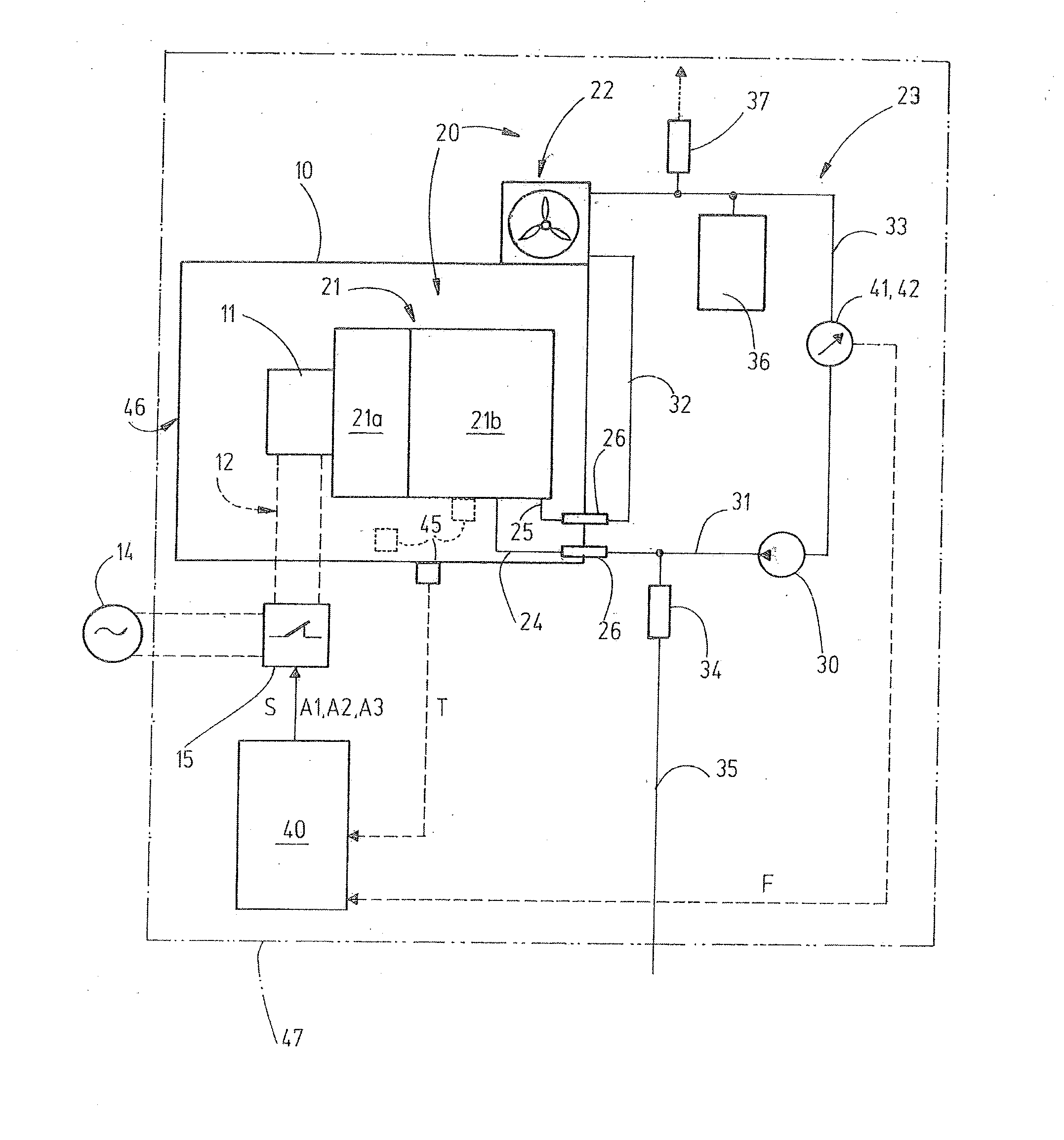
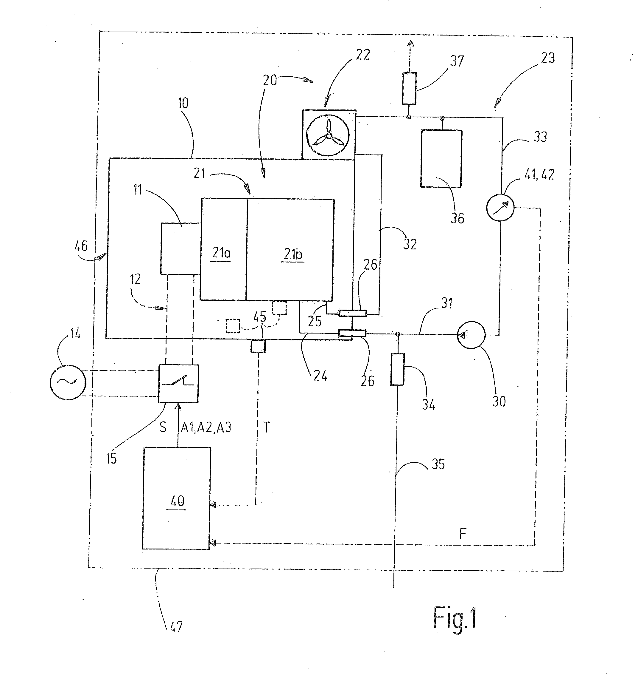
[0024]Referring now more particularly to the drawings, there is shown an illustrated explosion-protected housing 10 in an ignition protection type pressure-tight encapsulation (Ex-d) in accordance with the invention. One or a plurality of electrical and / or electronic components 11 are arranged in the housing 10. The illustrated component 11 is supplied with electrical energy via an electrical supply line 12. The supply line 12 is guided through a wall 13 of the housing 10 in a flameproof manner. The supply line 12, which can include two or more electrical conductors, in this instance is connected to a main voltage source 14.

[0025]A controllable separating device 15, such as a switch, is arranged in the supply line 12 or in at least one conductor of the supply line 12. In its separated state, the separating device 15 interrupts the voltage and current supply of the component 11. The separating device 15 can be switched into this separated state by means of a corresponding control sig...


PUM


Abstract

A pressure-tight encapsulated housing (10) having a temperature control device (20) including a first heat exchanger unit (21) arranged in the interior of the housing (10) and a second heat exchanger unit (22) arranged outside of the housing (10) and which are connected to one another via a liquid cycle (23). The liquid cycle (23) includes a feed line (24) and a return line (25) each connected to the first heat exchanger unit (21) and which each fluidically connect to a passage channel (27) of a respective leadthrough unit (26) arranged in flameproof manner in a wall (13) of the housing (10) so that the passage channel (27) extends through the wall (13). The control device (20) further includes a liquid monitoring sensor (41) for generating a liquid monitoring signal (F) characteristic of the filling of the passage channels (27) with liquid, and a monitoring unit (40) for receiving signals generated by the liquid monitoring sensor (41).

Description

FIELD OF THE INVENTION[0001]The present invention relates to a pressure-tight encapsulated housing comprising a temperature control device, which encompasses a first heat exchanger unit, arranged in the interior of the housing, and a second heat exchanger unit arranged outside of the housing. The two heat exchanger units are connected to one another via a liquid cycle. In this manner, components can be cooled and / or heated, as needed in the pressure-tight encapsulated housing.BACKGROUND OF THE INVENTION[0002]A housing of the foregoing type, for example, is known from WO 2010 / 132211 A1. The two heat exchanger units inside and outside of the housing, respectively, are connected to one another via coolant pipes, which are guided through the wall of the housing.[0003]The wall leadthrough of the pipes, however, can impact the flameproof guarantee of the housing. The pressure-tight encapsulated housing described in DE 101 52 510 A1 provides a coolant passage, having a pressure-tight barri...

Claims


Application Information

Patent Timeline
IPC IPC(8): H05K7/20H05K5/06
CPCH05K7/20281H05K5/06H05K5/069H05K7/20218
Inventor WALCH, OTTOPOIDL, JURGEN
Owner R STAHL SCHALTGERATE
Why Eureka
Try Eureka